Table of Contents
You May / Actually Highly Recommended
The Risk of Rushing into BitcoinThe risk is from yourself. If you are not mentally strong enough, you will not able to handle the volatile market. Tomorrow, it may rise by a thousand dollars but the next day may drop by two thousand dollars. You will become like the FOMO losers who buy when the price is high and sell when the price is low especially if you are here to get rich quick. When people asks you why you buy bitcoin and you only answer "to get rich" they will eat you alive. Question Checklist Before Buying More Bitcoin
1. Do you know how the current global monetary system is created and how it works?
2. Have you studied some previous monetary crisis'?
3. Do you know why bitcoin was created?
4. Do you know what bitcoin is and how it works?At least watch a short video how bitcoin works. 5. Do you know the benefit of bitcoin?
6. Do you know the challenges of bitcoin?
Until you understand them, you should not buy more bitcoin because not only you are leaving yourself vulnerable, your future actions will burden the entire cryptocurrency community and those who really needs cryptocurrency like the unbanks, the discriminated, etc. The best approach is to educate yourself first. Mirrors
0 Comments
1. Hack Administrative Access Windows 7The PC was designed for the user to only have standard user account privilege (near guest account) where the user only have the right to read and execute certain data and application. Unlike administrator account doesn’t have the privilege to modify the PC’s setting for example uninstalling admin’s program, editing the registry, modify the services, set the startup, etc. Here a method is explained for a standard user or non-user at all to gain administrative access. The method uses physical means through a bootable media such as CD or USB thumb drive to gain access to administrative command line (cmd.exe here) in order to create an administrator user using the vulnerability of sticky key (sethc.exe here). The simulation here uses Virtual Machine (VM) of Windows 7 since I don't want to mess with my real Operating System (OS) (using VM is a great alternative for home experiment). The concept is to use the vulnerability in Sethc.exe, more details can be referred to below video.
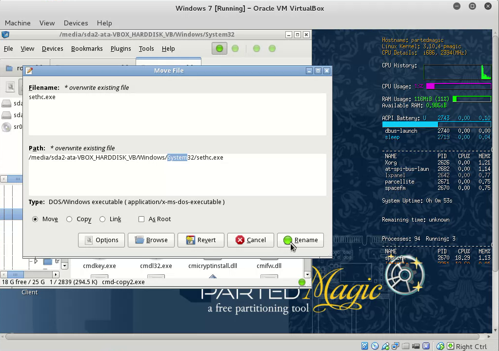
2. sethc.exe vulnerabilityThe goal is how to unleash command prompt at startup. Sometimes the safe mode to start command prompt is disabled so another method is needed. The method here is to use the vulnerability in sticky key, replace “sethc.exe” with “cmd.exe”. To do this anything that could have the permission to read and write data on system’s directory will do. On the field I need to execute this quickly to avoid suspicion, so I boot “FreeDOS” from USB with “NTFSParagon” in it to write “cmd.exe” on the host’s directory. I even brought my own cmd.exe because the limit of “NTFSParagon”. An easier way is to live boot an Operating System (OS) such as Windows, Linux, and MAC. The issue is the OS commonly used by people nowadays is heavy and large for this kind of job. If there’s a lighter way, why not (booting DOS was the lightest from my experience). I found a good light boot application for diagnosing a PC called Ultimate Boot CD (UBCD). Figure 1 shows Partition Magic was included in UBCD (a light Linux based for partition). Through here I can access on “C:\Windows\System32” using the “filemanager”, copy “cmd.exe” to (replace) “sethc.exe” shown on Figure 2. Restart and boot to Windows, then click shift 5x or more. A command prompt will show up as shown in Figure 3. (You can use Rufus, Universial USB, Yumi, Unetboot, or other softwares to make a bootable USB, just choose UBCD iso). (click image to enlarge). 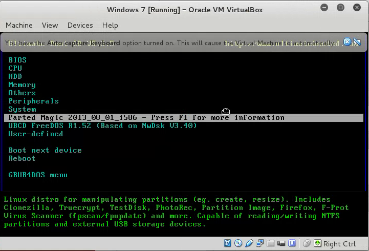
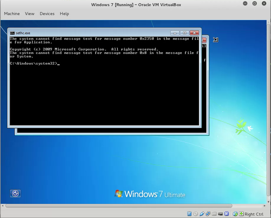
Through here a command line with administrator privilege was summoned. It’s available to create a user and promote any user up to administrator. The syntax to do so as followed:
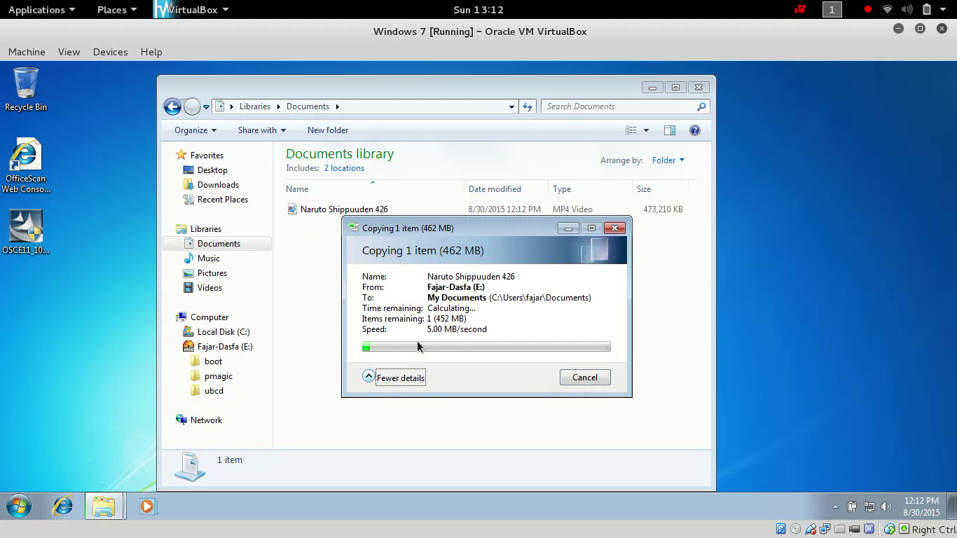
3. USB Access Through Trend Office ScanAfter gaining administrator privilege then gaining access to USB thumb drive available. It’s identified that a software name Micro Trend Office Scan is responsible for controlling the device. But one flaw is found, it takes time to load the service thus giving the user a chance to disable the service even further disable the password, lastly even uninstall. The data was obtained by simulating the bypass of my own laptop, not even using my Windows but using a virtual machine with Windows 7 in it. Then I downloaded Micro Trend Office Scan, asked for trial for 30 days, and install in my Windows 7 virtual machine. In other words an environment similar to the host was created, not performing on the real host. As in Figure 5, “Micro Trend Office Scan” is responsible for blocking USB Thumb Drive Access. There’s a time limit to unblock this. At the beginning after restarting the PC:
This method is one at a time use only. I meant that you have to repeat these steps again if you reboot your PC. Further action needed if you want to maintain the access which will be explained at the next section. 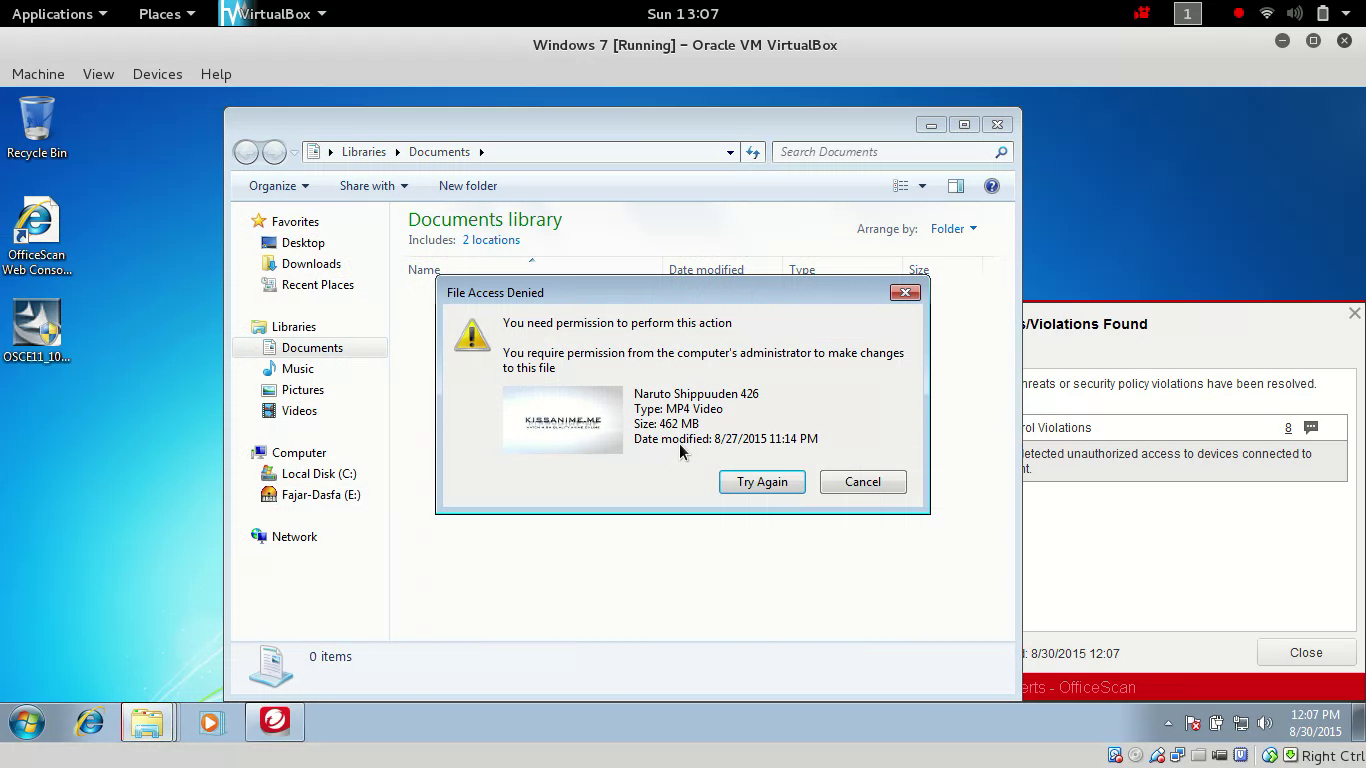
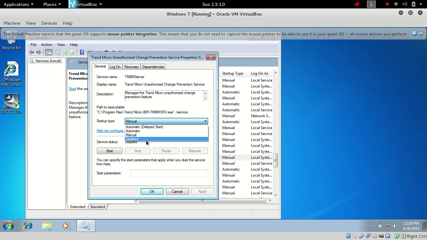
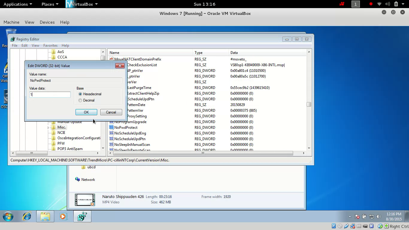
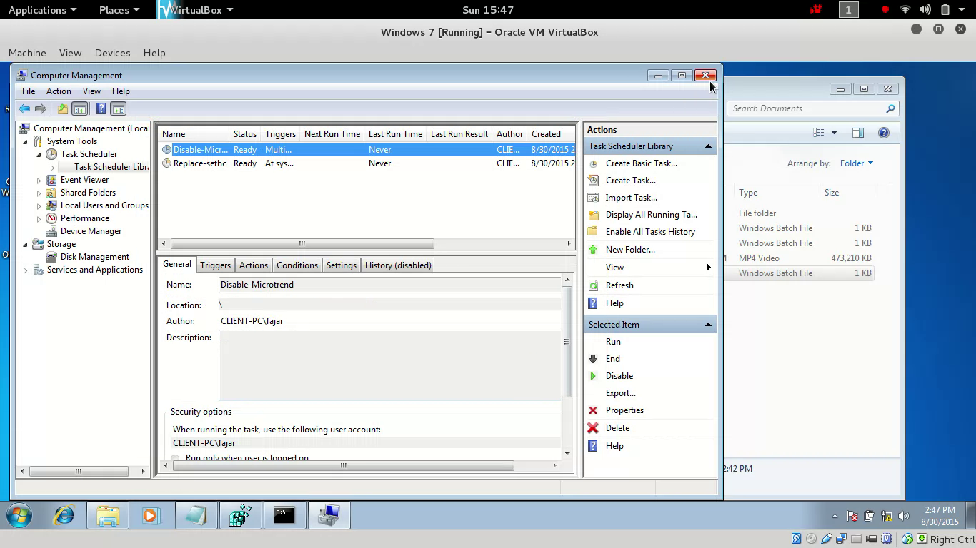
4. Maintaining AccessThe maintaining access here means that the steps on Section 3 don’t have to be repeated the next time we boot the PC. Instead we will configure for the steps above to run at startup, to do that we need to know the command line base of the above methods. Code 1 contains a simple command to replace “sethc.exe” with “cmd.exe”. Code 2 contains commands to stop and disable Trend Micro Unauthorized Change Service, followed by editing “NoPwdProtect” key registry.
The following can be done in “computer management” to add startups:
Mirrors
1. IntroductionIn electric circuit star and delta circuit consist of 3 loads which in star circuit they are connected in form of a star while in delta circuit are connected in delta form as in Figure 1. 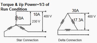
The application is usually used in (Alternate Current) AC motor where it has to start slowly. Starting the motor through a high current immediately could blow the motor as the starting current equals to the normal current multiplied by v3 (=v3 x I). It’ll be fine if the current is 5A (ampere) (I_start=v3 x 5 A=8.66 A), what happens if it’s 50A it’ll be (I_start=v3 x 50 A=86.6 A). The difference between 50A and 86.6A is quite significant. Therefore a switch to initially start a motor through star condition (low current) is needed, then after a while controlled by a time change the circuit to delta (high current). Full diagram can be seen in Figure 2. 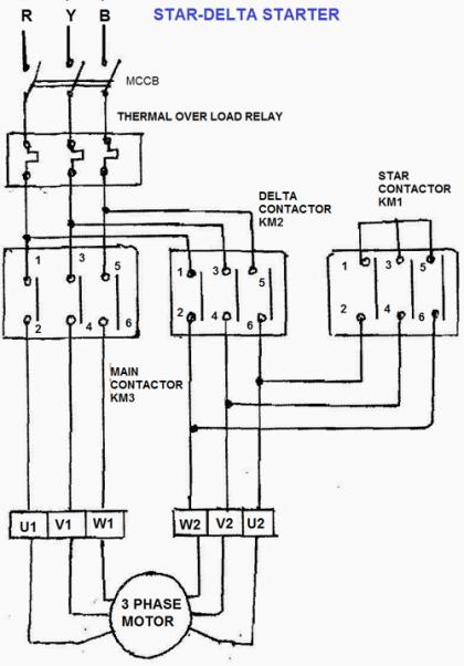
2. Simulation DesignFor the experiment here we have limited resource, we don’t have the star-delta motor which made me think whether there’s an alternative to do the star-delta motor simulation. I got an idea of using a low voltage lamp or LED as an indicator by using the brightness of the lamp. Instead I’d use 3 resistors (1 K? for this experiment) to form both star and delta circuit. We’ll see the brightness of the lamp instar and delta circuit, and for this we’ll use Direct Current (DC). Since there’s only positive (+) and negative (-) for the source we need to figure out an alternate circuit (AC have 3 sources R-S-T). For star circuit is T circuit and for delta circuit is Pi circuit in DC as shown in Figure 3 (If I have time I’ll include the calculation). Figure 3 shows that the current passed through T circuit is smaller which should be used as initial circuit, and Pi circuit passed larger current which should be switched later afterwards. 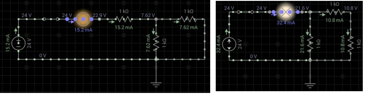
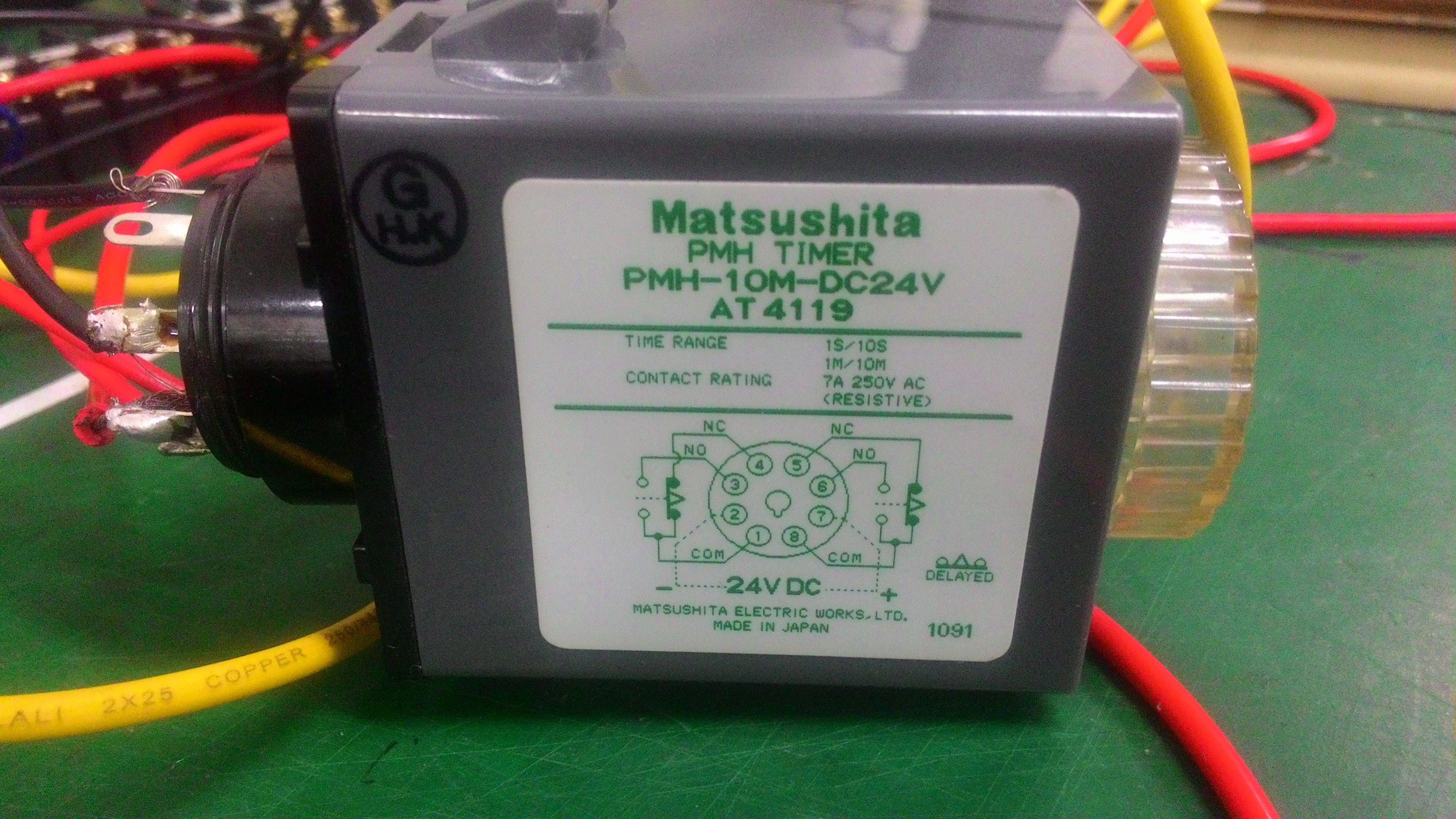
To realize this experiment we used:
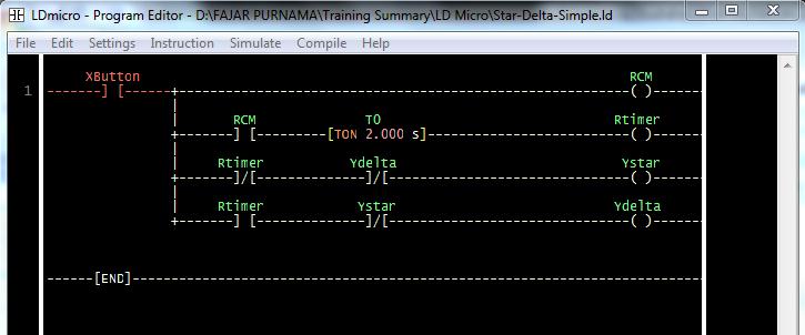
An image of a simulation can be seen on Figure 4 where 1 relay as a switch to T circuit and the other one as a switch to Pi circuit. A simulation video using android application EveryCircuit is included on this same folder as this report excluding the timer. On the real application based on the ladder diagram on Figure 5 a timer will be set where initially will start the relay of T circuit (Pi circuit disconnected). After 2 seconds (or any set time) the timer will disconnect the relay of T circuit and connecting the relay of Pi circuit. 
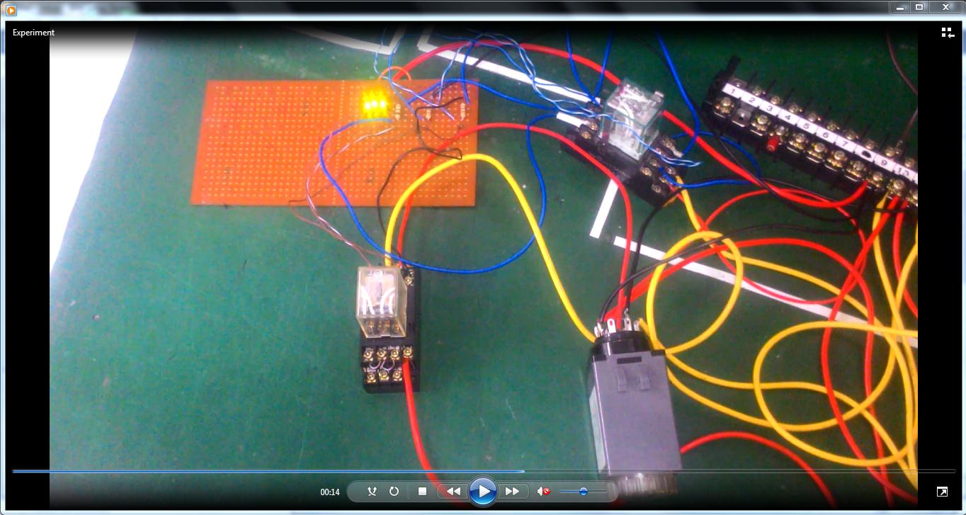
3. Experiment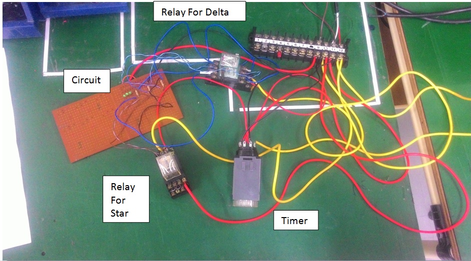
4. ConclusionThe simulation for this circuit succeeded and can be implemented to build a real star-delta motor. The motor will initially be slow, and then a few seconds the motor will be faster. This kind of design is used for devices which isn’t allowed to start at maximum power from the start (for example the motor could explode) since the initial current is v3 greater than the normal power thus a lower current is used when starting. But we want to use the device in its maximum power so a timer is needed to change the current to the maximum after passing the initial stage. Using relays and timers in terms of time we can create different conditions with just a few circuits. For example we can set the time of when we want the air conditioner to turn on or off (other machines as well).1. IntroductionA chamber room in this experiment is known as an automation circuit. It’s designed to keep the room temperature at a certain degree. This chamber room is chosen as one of the training for automation. Here we learned how to design our concept using ladder logic, and then realize the physical circuit by using a few automation devices. The purpose of this training is to introduce to few automation devices which are relay, contractor and thermal couple. We built an experimental chamber room based on the ladder diagram we designed. 2. Experiment DesignThe chamber room how we wanted to work here is by using a heater to heat a room, when the room temperature is lower than the set temperature (cooler) the heater will be on to heat the room, but if it is higher (hotter) the heater will turn off. The heater will turn on again when the temperature drops. 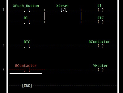
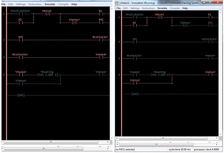
Figure 1 shows the ladder diagram of chamber room we wanted to make. The concept is locking the room temperature. a. When the button is pushed an electric current will flow to relay R1 (pin 13 to 14) and activate thermocouple (RTC) while R1 (pin 9 to 5) will lock the current even if the push button is off (the light will remain on). The left side is the positive node connected to the power supply while the right side connects to the ground. The numbers on Figure 1 are pins which will be explain later on. b. The thermocouple will activate the Contractor and activates the heater. c. The thermocouple will sense the room temperature and when it reaches the set temperature (heats), the thermocouple will switch off (cut the line). d. Electric current will stop flowing to contractor hence shutting down the heater. e. After a while the room temperature will drop (cools down) and again activating the thermocouple (let current flow) and activates the contractor with the heater. f. The cycle will go on locking the room temperature. The relay (R1) is set to lock the flow of electric current to the thermocouple since we’re using a push button. Without it the circuit will turn off after we release the push button while we want it to keep turned on even if we release the push button. For the ladder diagram above we use a push button, reset button, relay, thermocouple, contractor, and light bulb as an indicator while we use a solder to heat the heat sensor on the thermocouple. Figure 2 shows a relay: a. as in Figure 1 pin 13 will connect to the reset button (source of 220 V) and pin 14 will go to the ground. b. Pin 9 is normally close (NC) to pin 1 (it connects when no current flows), c. but normally open (NO) to pin 5 (the switch from pin 9 will turn to pin 5 when current flows) thus locking the thermocouple even the push button is released. d. The reset button will cut the flow if pressed. 
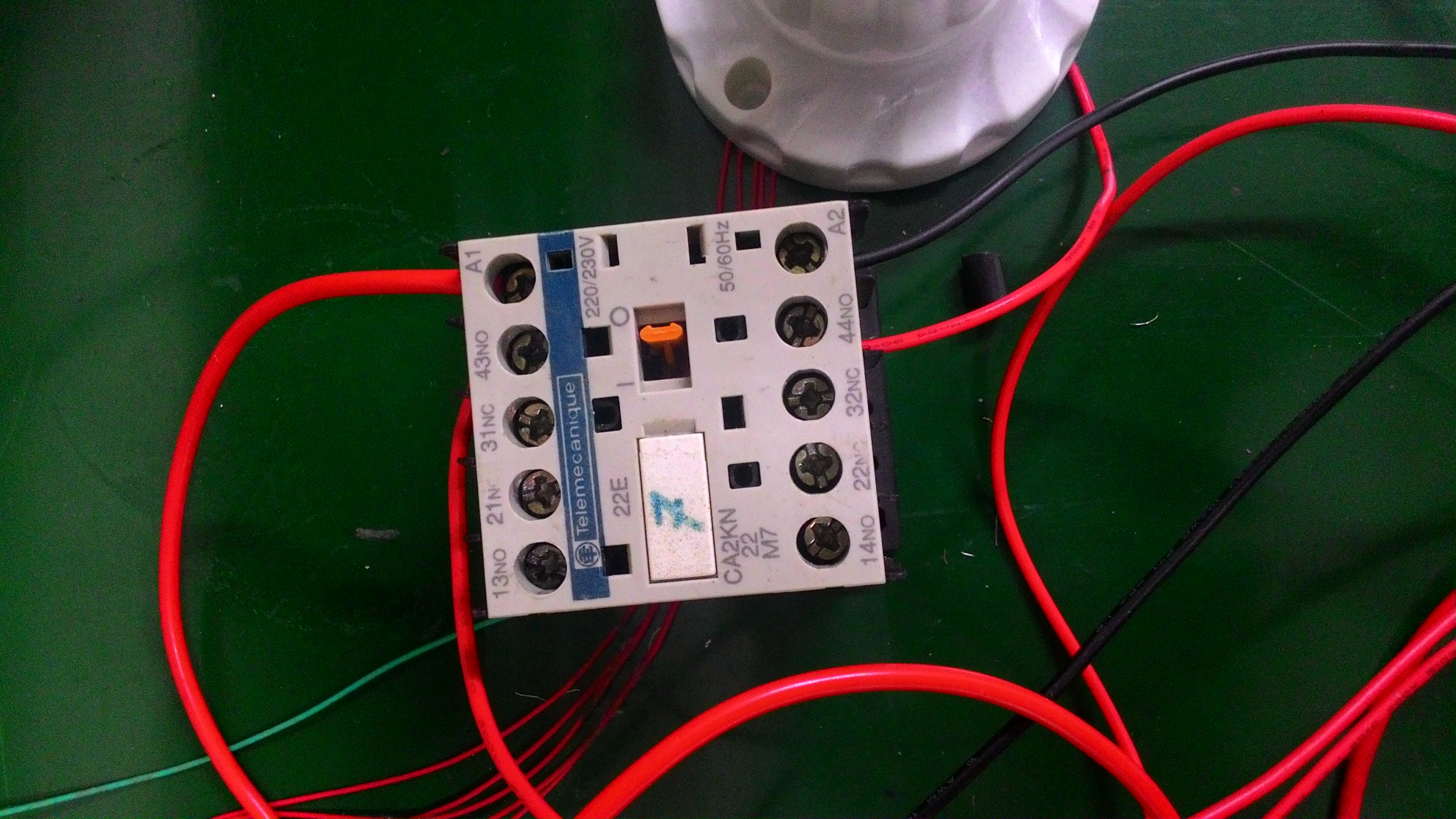
Figure 3 shows the thermocouple (focused on the circuit) which: a. pin 7 and 8 connects to the power supply like the relay. b. Same as the explanation for Figure 2 (relay) pin 4 is NC to pin 6 but NO to pin 5. c. The heat sensor will be connected to pin 1 and 2. d. When electric current flows pin 4 will connect to pin 5, e. and if the heat sensor is heated to certain degree, pin 4 will disconnect from pin 5 and connect to pin 6 which will cut off the heater. Figure 4 is a contractor which in ladder diagram should not be needed (simplify) but in actual circuit the thermocouple cannot hold high electric current thus needs the help of a contractor. Since this is just a simple experiment we will use a light bulb as an indicator in replacement of heater. We will use an external heater which is a solder in heating the heat sensor. 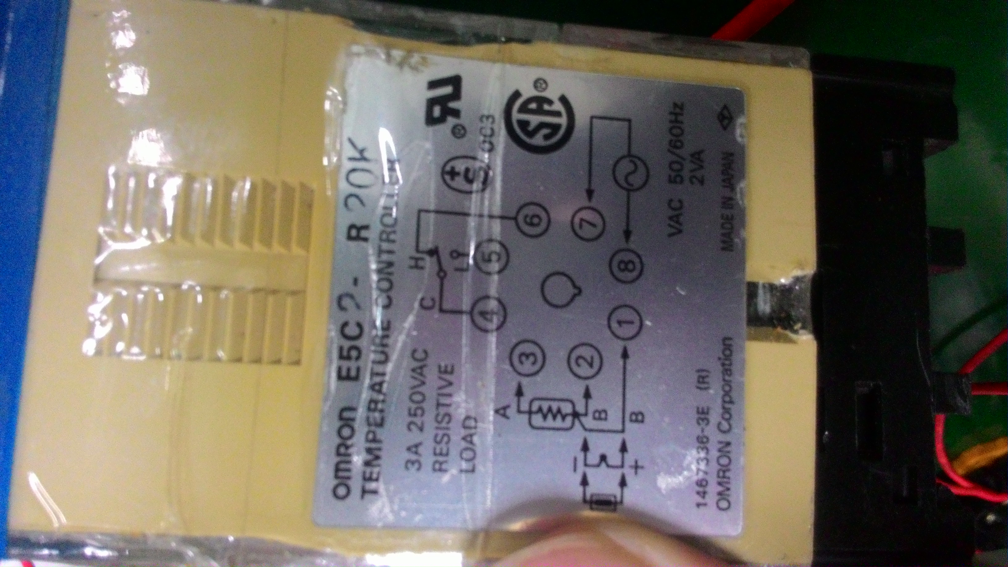
3. Running the ExperimentSince it’s a practice we only connect the wires based on Figure 1, it’s not surprising that Figure 5 seems unpleasing to the eye. This will immediately be disassembled afterwards since the other devices will be use for other projects. It’ll be best to refer to this video first because it might be difficult to understand this writing if we don’t have experience in automation. 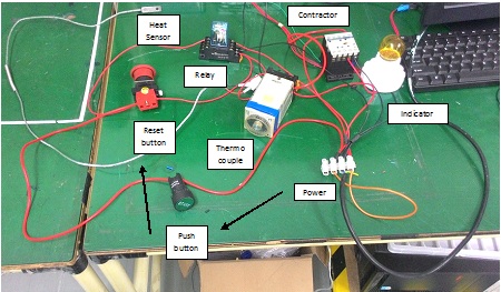
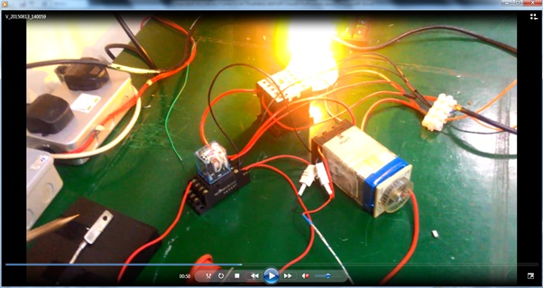
In Figure 6, just pushing the push button once the light will turn and remain on. It’s because the relay is also connected to the power supply and is in connected position to the thermocouple. As of Figure 1 explanation the relay locks the current. Then we tried heating the heat sensor using a solder in Figure 6. After while the lights goes out which proves our statement/explanation of Figure 4 (current won’t flow to bulb when heated to 100o C in this experiment). In Figure 7 the solder was released which lets the heat sensor to cool down and turned the light again. Figure 1 is the ladder diagram for the actual circuit, in Figure 8 is the simulation of what happen to the actual circuit which includes the heat sensor in the ladder diagram. a. The heater turns on when the button is pushed heating the sensor. b. We assumed that it takes 2 seconds to heat it up. c. After 2 seconds (assumed reached targeted temperature) activates the sensor and will cut the line. d. The heater will turn off. 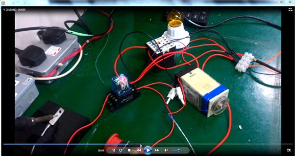
4. ConclusionAbove is only simulation of a chamber room not real experiment. While the chamber work like the Air Conditioner (AC), Iron, or oven which controls the surrounding temperature this one is only to simulate the use of thermocouple where the heat sensor is manually heated up with a solder, even the relay only functions to keep the circuit alive. Thus the experiment above allowed us to able to create a concept of chamber room, design the ladder diagram, and implement them through relays and thermocouple. In summary the experiment succeeded in simulating a chamber room. The light bulb is the indicator whether the temperature is below set point or above, it lights when it’s at low temperature. The heat sensor connected to thermocouple was heated using a solder and sets it to high temperature, ultimately kills the light bulb (cuts the electric current). It will turn on again when it cools down. Mirrors

How to Register

FeaturesTrading Pairs
Trading View
Margin
Other Menus
Deposit and WithdrawWithdraw Fees:
Depositing from Japan Post Bank https://lbry.tv/@0fajarpurnama0:e/btcbox-cryptocurrency-trading-platform:d Join LBRY Invite Your FriendsUse my code HNRCWSLFLF if you have not register and we both get ¥500 valid until end of March. After that, use your code to invite your friends and you can get $500 for each invites. Maybe they'll have another campaign in the future. 
More DemonstrationMirrors:
I don't have any experience registering outside Japan, please comment if you know. |
Archives
August 2022
Categories
All
source code
old source code Get any amount of 0FP0EXP tokens to stop automatic JavaScript Mining or get 10 0FP0EXP tokens to remove this completely. get 30 0FP0EXP Token to remove this paypal donation. get 20 0FP0EXP Token to remove my personal ADS. Get 50 0FP0EXP Token to remove my NFTS advertisements! |


 RSS Feed

