CatatanArtikel ini merupakan tugas dari mata kuliah S1 saya mengenai penulisan penelitian dimana intinya diajar bahwa tulisan penelitian kebanyakan terdiri dari Abstrak, Pendahuluan, Tinjauan Pustaka, Metode Penelitian, Pembahasan, Penutup, dan Daftar Pustaka. Walaupun mata kuliah ini mengajarkan lebih detil mengenai isi masing-masing BAB, namun saat itu saya belum mampu menyerap detil itu seutuhnya di tugas ini. AbstrakSecara logika pengaturan resolusi dan fps pada video streaming seharusnya berpengaruh terhadap besar throughput. Tetapi di software Adobe Flash Media Live Encoder ada pengaturan bitrate, inilah yang yang berpengaruh terhadap besar throughput. Resolusi dan fps (frame per second) kelihatan pengaruhnya terhadap bitrate. Penelitian ini adalah pembuktian bahwa pernyataan tersebut benar. Manfaat untuk kedepannya, selain mengetahui throughput yang dihasilkan dari berbagai macam pengaturan di software Adobe Flash Media Live Encoder, pengaturan yang sesuai akan didapatkan. Penelitian ini menggunakan dua komputer yang terhubung pada jaringan yang sama. Komputer pertama melakukan video steaming melewati komputer kedua yang mengukur throughput yang dihasilkan komputer pertama. Software yang digunakan untuk mengukur throughput adalah Wireshark. Pengukuran throughput dilakukan pada variasi resolusi, fps (frame per second), dan bitrate. Lalu throughput rata – rata dari bervariasi resousi, fps, dan bitrate akan dibandingkan. Dari hasil penelitian, terbukti bahwa throughput rata – rata yang dihasilkan sesuai dengan pengaturan bitrate. Tidak terlihat dampak dari pengaturan resolusi dan fps. 1 Pendahuluan1.1 Latar BelakangKualitas video seperti besar pixel gambar dan fps (frame per second) mempengaruhi throughput. Semakin besar pixel gambar maka semakin besar frame data yang dikirimkan. Begitu juga halnya dengan fps. Telah dipasang web cam di Lab Komputer, jurusan Teknik Elektro, Universitas Udayana. Pemasangan web cam untuk memperlihatkan kegiatan lab melalui web. Secara nyata belum diketahui throughput yang dihasilkan dengan berbagai pengaturan fps (frame per second), resolusi dan bitrate. Pada penelitian ini akan diamati throughput yang dihasilkan dengan berbagai pengaturan fps (frame per second), resolusi, dan bitrate menggunakan software Wireshark. 1.2 Rumusan MasalahBagaimana throughput yang dihasilkan dengan berbagai variasi pengaturan fps (frame per second), resolusi, dan bitrate? 1.3 Tujuan PenelitianMengetahui pengaruh pengaturan FPS (frame per second), resolusi dan bitrate terhadap throughput yang dihasilkan pada software Adobe Flash Media Live Encoder. 1.4 Manfaat Penelitian
1.5 Ruang Lingkup dan Batasan Masalah
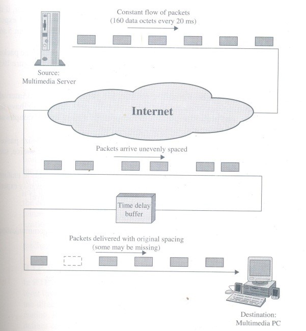
2 Kajian Pustaka2.1 ThroughputThroughput merupakan besar data yang dikirimkan dibagi dengan waktu yang dibutuhkan untuk besar data sampai ke tujuan dalam komunikasi 1 arah. Throughput diukur dalam bit/second atau byte/second (Gómez, 2005). Aplikasi seperti VOIP (voice over IP) dan video sensitif terhadap delay dan jitter. Delay merupakan waktu yang dibutuhkan suatu paket untuk terkirim dari asal sampai tujuan. Jitter adalah variasi delay. Aplikasi seperti ini memerlukan delay yang kecil (kira-kira 150 milisecond). Oleh karena itu throughput harus dijamin dari asal ke tujuan (Farrel, 2009). 2.2 RTP (Real-Time Transport Protocol)RTP merupakan transport protocol untuk aplikasi yang berbasis real-time. Aplikasi yang berbasi real-time dapat berupa audio dan video conferencing, live video distribution, shared workspaces, remote medical diagnosis, telephony, command dan control systems, distributed interactive simulations, games, dan real-time monitoring.` Dengan perkembangan LAN (Local Area Network) dan WAN (Wide Area Network) kecepatan tinggi maka memungkinkan untuk aplikasi berbasi real-time untuk dijalan di jaringan berbasis IP (Internet Protocol). Hal secara umum yang diperhatikan dalam applikasi berbasis real-time adalah timing (waktu yang tepat). Dimana timing penerimaan paket harus sesuai dengan timing pengiriman paket. Oleh karena itu delay dan throughput merupakan hal yang umum untuk mengukur kualitas (Stallings, 1998). 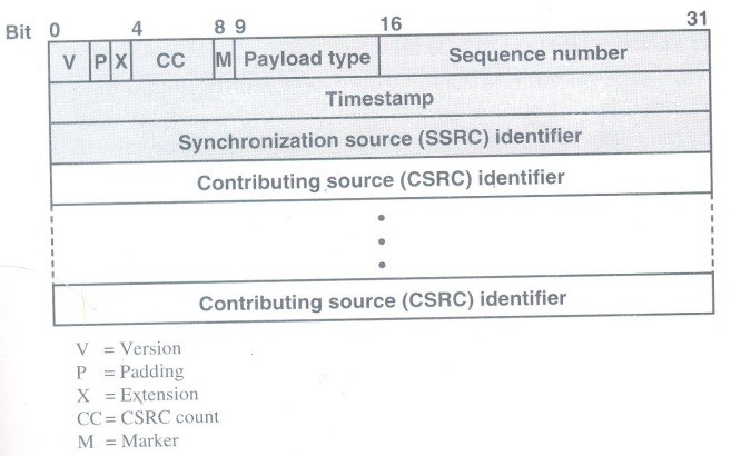
2.3 Adobe Flash Media Live EncoderMerupakan software media encoder yang dapat menangkap audio dan video serta stream video dan audio ke Adobe Media Server atau Flash Video Streaming Service (FVSS) secara real-time. Software ini mampu broadcast kegiatan secara langsung seperti olahraga, konser dan lain-lain. (Adobe, 2013). 2.3 WiresharkWireshark merupakan software network protocol analyzer yang terkenal di dunia. Bisa juga menangkap trafik pada suatu jaringan computer. Software ini de facto (dan sering dikatakan de jure) standar dari berbagai industry dan institusi pendidikan. Wireshark dikembangkan oleh banyak ahli jaringan di seluruh dunia dan merupakan proyek yang berlanjut mulai 1998 (Combs, 2013). 3 Metode Penelitian3.1 Alat yang digunakanBerikut adalah daftar alat yang digunakan:
3.2 Cara PenelitianPertama, alat didesain sebagai berikut: 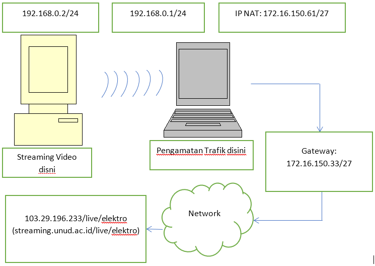
Kedua, memulai manangkapan paket dengan software Wireshark pada laptop. Paket yang ditangkap adalah pada wireless LAN. 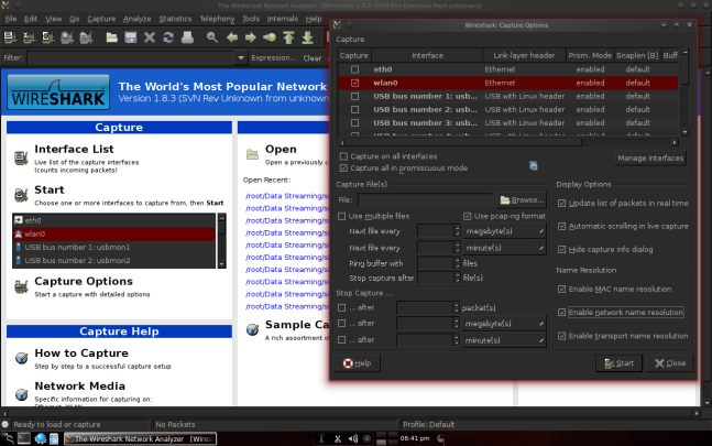
Penangkapan paket di saring agar hanya menangkap paket yang dikirim oleh video streaming, yaitu 192.168.0.2. 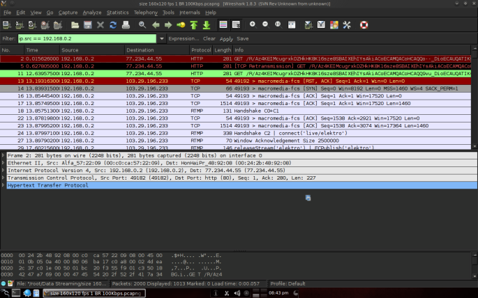
Untuk melihat throughput maka dipilih menu statistics lalu dipilih IO graph. 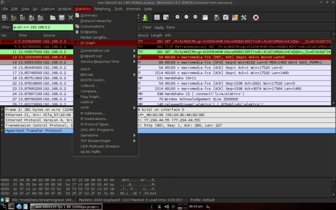
Sama seperti penangkapan paket, disaring agar hanya terlihat bit yang lewat dari 192.168.0.2. 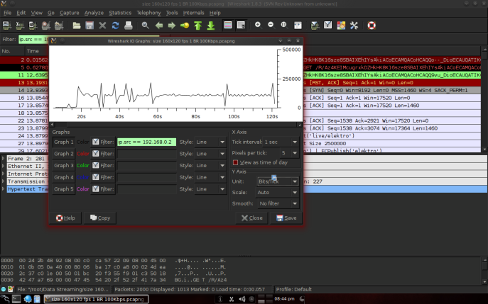
Ketiga, mulai streaming video dengan software Adobe Flash Media Live Encoder dengan pengaturan disesuaikan pada rumusan masalah. 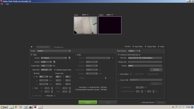
Keempat, setelah 2 menit streaming dihentikan. Keenam, penangkapan paket pada Wireshark dihentikan dan hasilnya di simpan. Ketujuh, kembali ke langkah kedua dengan langkah ketiga pengaturan yang berbeda (melanjutkan dari rumusan masalah). Jika semua pengaturan telah dicoba maka pencarian data selesai. 3.3 Analisis DataDengan menggunakan software Wireshark maka dapat dilihat throughput dalam bentuk grafik. Sumbu horizontal menunjukan waktu dalam detik sedangkan sumbu vertikal menunjukan data dalam bit. 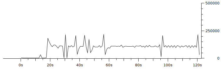
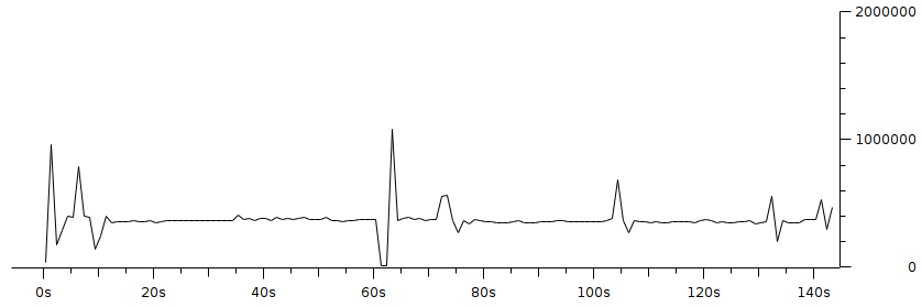
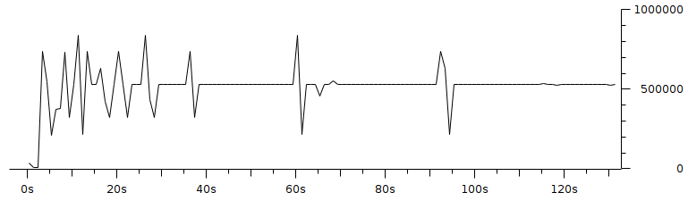
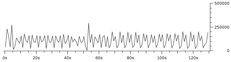
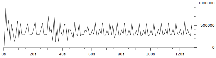
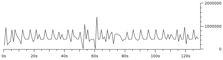
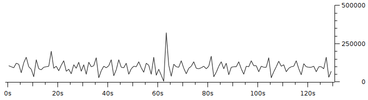
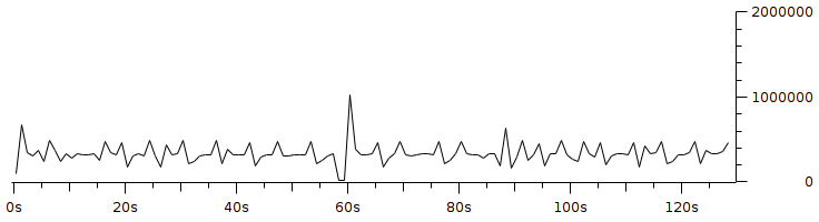
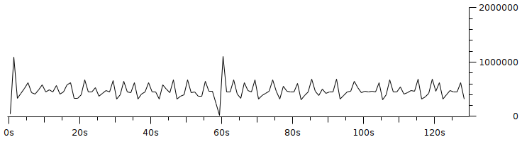
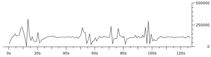
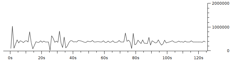
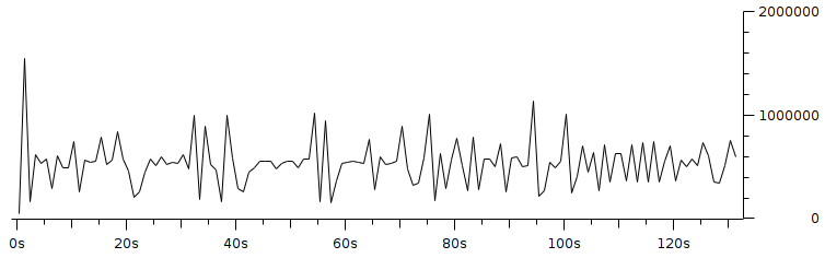
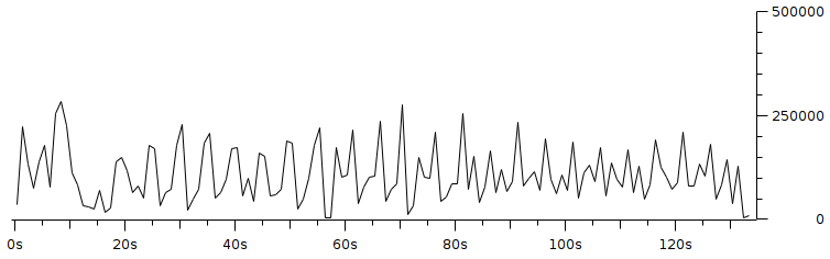
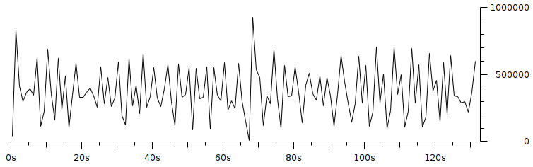
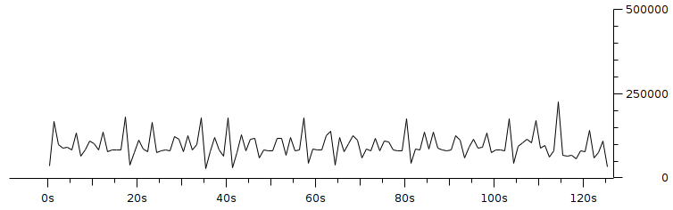
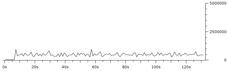
4 Hasil dan Pembahasan4.1 PembuktianPembuktian bahwa throughput rata – rata sama dengan pengaturan bitrate dapat dilihat tabel berikut:
5 Penutup5.1 SimpulanDari hasil percobaan, terbukti bahwa throughput rata – rata sepenuhnya dipengaruhi oleh pengaturan bitrate. Walaupun pengaturan resolusi 160x120, 320x240 dan fps 1, 5, 10, jika bitrate diatur 100Kbps maka throughput rata – rata 100Kbps, pengaturan bitrate 350Kbps maka throughput rata – rata 350Kbps, pengaturan bitrate 500Kbps maka throughput rata – rata 500Kbps dan seterusnya. 5.2 SaranWalaupun throughput rata – rata sama dengan pengaturan bitrate grafik yang dihasilkan bervariasi dengan pengaturan resolusi dan fps yang berbeda – beda. Dari penelitian ini, resolusi dan fps sesungguhnya tidak diamati. Delay, jitter, atau parameter selain throughput tidak diteliti di artikel ini. Hal – hal tersebut dapat dijadikan sebagai penelitian lanjutan dari penelitian ini. Software yang diteliti adalah Adobe Flash Media Live Encoder, maka dapat melakukan penelitian ulang dengan menggunakan software lain. Daftar Pustaka
0 Comments
Transmisi citra pada perangkat jaringan sensor visual nirkabel platform imote2 berbasis ieee 802.15.4 zig bee embedded linux from Fajar Purnama
Notes
Table of Contents
AbstractIn recent years, the wireless sensor network (JSN) has provided breakthroughs in the field of monitoring from monitoring rainfall in gardens to monitoring heart rate in the health sector. This technology is known for its very low and simple energy consumption, and is currently being developed so that it can operate without a power source, but instead uses the available ambient energy such as using the energy input of a TV station's electromagnetic waves. JSN initially focused on data that could be sent at a low bit rate channel capacity. In this research, it is more to JSN with a higher bit rate channel capacity in order to transmit multimedia data specifically here is image transmission, so that the term JSN can be reduced to a wireless visual sensor network (JSVN). The platform used is Imote2 with a radio based on IEEE 802.15.4 ZigBee and the main characteristic of this research is implementing an embedded Linux system, which has never been done before. So far, there are no publications that describe the image transmission scheme in Imote2 Linux, in other words there is no information related to image transmission. This research discusses in detail the image transmission scheme between the author's version of Imote2 Linux and the scheme so that it can be used as a testbed, starting from applications written in C, compiling some testbed requirements, to implementing the testbed. The rest of the performance of Imote2 Linux is tested by transmitting the image without compression and with the JPEG2000 standard compression where the compression is carried out on the Imote2 Linux embedded system by the OpenJPEG software. The results show a significant difference between uncompressed and compressed transmission. Chapter 1 Introduction1.1 BackgroundWSN (wireless sensor network) is a wireless network system that uses sensor devices to obtain information. These sensors are distributed in an area that are connected wirelessly (forming a network) to collect information around them as in Figure 1.1. This WSN has been applied in the civil, medical, and other fields (Shwe et al, 2013). There are several types of sensors, including temperature, motion, acidity, sound, and camera sensors. This research uses WVSN (Wireless Visual Sensor Network) which is a camera sensor-based WSN. 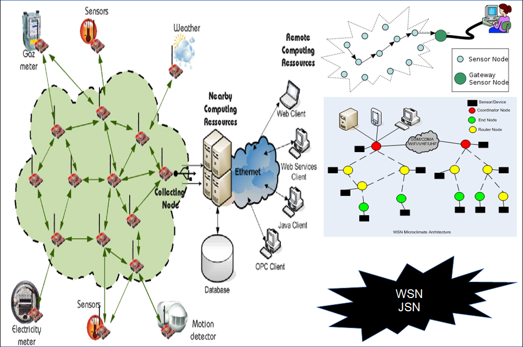 One example of the application of WSN is the research of Garcia-Sanchez (2010) on monitoring of wild animals on transportation infrastructure in the wild. Things that are monitored are animal interactions such as the frequency and time the animals cross the road or underpass, the length of time the animals have been there, and how the animal's attitude towards the transportation infrastructure. From this monitoring, it can be seen whether the transportation infrastructure is safe, attracts the attention of animals, the overall condition of the transportation infrastructure and the natural conditions around it. Monitoring is carried out by installing camera sensors and motion sensors on the Imote2 platform in the transportation infrastructure area such as the underpass entrance gate, in the underpass, the edge of the highway, above trees, or in ravines as shown in Figure 1.2. Several factors such as no power source (resource), an environment that does not allow the installation of large devices such as ravines, danger zones, uneven terrain, and sensitive environmental conditions (tend to attack the device or avoid the device), or the time factor that requires immediate monitoring so that it is impossible to spend time on large equipment installations, and many other factors, a similar example in the military field to detect the presence of an enemy must use a minimalist and small device so that it is not easily detected, for this matter WSN is an option because it is practical to apply. 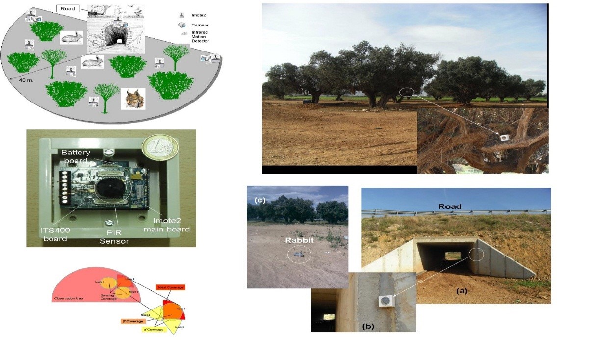 Current WSN research leads to energy savings while maximizing performance in other words, getting as much information as possible with the minimum energy consumption. This is because WSN has limited resources and limited computing capabilities. Imote2 itself uses 4 AAA batteries as a power source, has a processing capability of 13-416 MHz, 32 MB program memory, 256 kB of RAM (Random Access Memory) as a temporary storage place at the processing stage, and a maximum transmission rate of 250 kbps point-to-point. Even though Imote2's specifications are superior to other platforms as shown in Table 1.1, it is still far from being compared to PCs (Private Computers) which now have a minimum specification of over 1 GHz processor, over 1 GB RAM, and over 50 GB hard disk capacity. 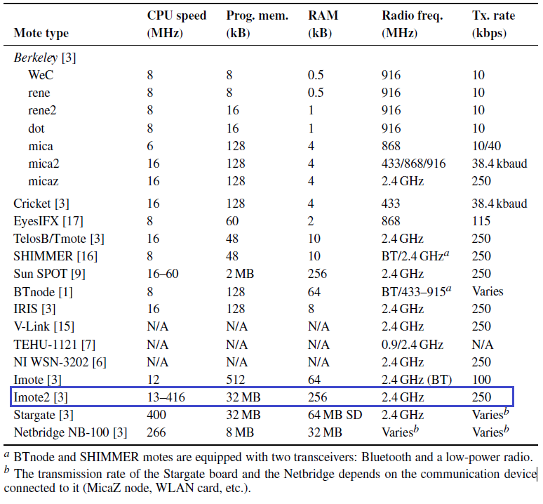 From these limitations, one of the efforts to save is the determination of the right transmission media. There are many types of standards for wireless transmission media such as WLAN (Wireless Local Area Network), Broadband Wireless, and WPAN (Wireless Personal Area Network). WLAN standardized on IEEE 802.11 has a wide range over 1 km with a max data rate of 54 Mbps on IEEE 802.11g, this standard is more suitable for wireless communication on computers. Broadband Wireless has a wider range with a max data rate of IEEE 802.16m 100 Mbps, better known as WMAN (Wireless Metropolitan Area Network). However, the results of previous research, namely research by Wiasta (2012), Natha (2012), and the author himself Purnama (2013), are not efficient in transmitting binary data using WLAN. The results are far compared to using the WPAN standard, which can be seen in Figure 1.3. For portable devices, the IEEE 802.15 WPAN standard is provided. IEEE 802.15.1 Bluetooth provides a max data rate of 723.2 kbps with a range of 10 meters. It is commonly used for voice and data transmission, applied to cellphones and gadgets. IEEE 802.15.2 regulates communication between WPANs and other wireless networks. IEEE 802.15.3 HR-WPAN (High Data Rate Wireless Personal Area Network) with a data rate of 11-55 Mbps with a range over 70 meters is commonly used for multimedia. Suitable for use on WSN is the IEEE 802.15.4 LR-WPAN (Low Data Rate Wireless Personal Area Network) standard because it is low power consumption and data rates of 20, 40, 250 kbps point-to-point with a range of 10 meters (Ahmad, 2005). IEEE 802.15.4 develops the PHY layer, MAC layer, and NWK layer, while Zigbee develops the full application layer in Chapter 2. The transmission limitation in IEEE 802.15.4 Zigbee is the maximum data rate of 250 Kbps point-to-point with PHY layer, the maximum packet size is 127 bytes minus 89 bytes header. Fragmentation and reassembly are not performed at the NWK layer, therefore the application layer must be developed for fragmentation and reassembly and adapted for image transmission (Pekhteryev, 2005). %20Imote2%20dengan%20WLAN%20.PNG) %20catu%20daya%20WLAN.PNG) %20dengan%20LR-WPAN.PNG) Another effort is to use a lightweight operating system. Previously Imote2 worked on Intel Platform X. After Imote2 moved to Crossbow, Intel Platform X was no longer being developed because Crossbow released its own operating system. The operating system used is most of the operating systems developed by communities such as SOS (Simple Operating System) but SOS has been discontinued since 2008. Currently, it is TinyOS and most recently Linux. Most publications on the web use TinyOS. Embedded Linux is now being developed due to the limitations of TinyOS such as complex routing. The embedded Linux community thinks the Linux operating system on Imote2 can overcome these limitations. However, embedded Linux on Imote2 is still new and under development (Kasteleiner, 2010). The main reason Linux is used is because it is opensource, which means it is free, open and can be developed by anyone. This research leads to embedded system Imote2 Linux. Previous work successfully embedded Linux into the Imote2 platform and successfully sent a maximum of 28 bytes of random data. In this work the function will be extended so that Imote2 Linux can transmit images with IEEE 802.15.4 ZigBee-based radios. After being able to transmit, the Imote2 Linux transmission performance will be observed. 1.2 Problem
1.3 Research Objective
1.4 Research Benefit
1.5 Scope of Problem
Chapter 2 Literature Review2.1 Previous ResearchThe previous research is the implementation of embedded Linux on the Imote2 WSVN platform. First Imote2 uses the operating system from Crossbow. After that TinyOS is installed, now we try to use embedded Linux. There are 3 things discussed, namely the embedded Linux installation procedure, post-installation configuration, and observed the performance of the Imote2 WSVN platform by measuring the memory consumed and the electricity consumed when transmitting binary data. The installation procedure includes cross-compiling the Linux kernel and drivers to the ARM architecture used by Imote2, setting up the bootloader and filesystem, and embedding the bootloader, kernel, and filesystem to Imote2 using the OpenOCD chip debugger software. To do this, you need a computer with the Linux operating system. Post-embedding / entry is activating IP (Internet Protocol), SSHD (Secure Shell Daemon), and radio networks via Telnet. The commands for configuring this are common in Linux based on Debian, Ubuntu, and the like. The final stage of the research is to observe the performance of binary data transmission at a distance of 10m, 20m, and 30m. The transmission was tested on 2 types of wireless transmission media, namely IEEE 802.11 WLAN and IEEE 802.15.4 Zigbee also called LR-WPAN. It is necessary to add a TP-LINK WLAN power supply and radio device to implement WLAN. A daughter board is created to connect the device. In terms of software, a driver is needed. While the Zigbee implementation is available in Imote2, all you need to do is run the driver and create a script to transmit binary data. In the final result Zigbee is more efficient in terms of consumption of voltage and electric current can be seen in Figure 2.1, Figure 2.2, and Figure 2.3. The value of electric power consumption is the result of the multiplication of voltage and electric current in the previous figure, namely Figure 1.2 (Natha, 2012, Wiasta, 2012, Purnama, 2013). %20tegangan.PNG) %20arus.PNG) %20tegangan.PNG) %20arus.PNG) %20tegangan.PNG) %20arus.PNG) 2.2 State of The ArtThis research is a continuation of previous research that will examine the performance of the WSVN Imote platform with the embedded Linux operating system in transmitting images via IEEE 802.15.4 Zigbee-based transmission media. If previously only transmitting binary data, this time is transmitting images. It is preferred to use IEEE 802.15.4 Zigbee-based transmission media because it was previously proven to be more efficient. The idea to examine image transmission with 4 different scalabilities based on wavelets (research stage in Chapter 3) was obtained from the research of Nasri (2010). Nasri's research (2010) examined the application of JPEG2000 in distributive image transmission in WSVN. In detail, the WSVN scheme is divided into 7 clusters (7 groups of WSVN devices) where each cluster is given a part of the standard JPEG2000 compression stage (JPEG200 can be seen in sub-chapter 2.6) can be seen in Figure 2.4. With this scenario the idea emerged to transmit images with different scalability based on the JPEG2000 standard in the research at this writing. 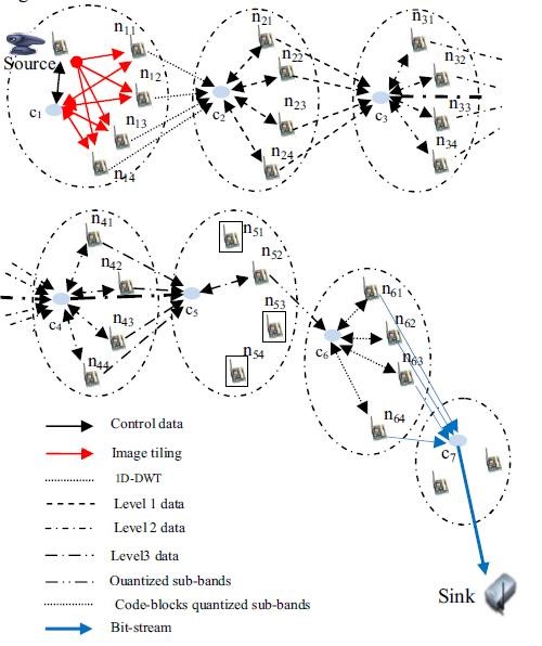
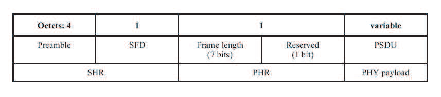
In summary, the results of the highest energy consumption are in the first and second clusters, then energy consumption decreases from the second cluster to the destination. The results were obtained using a special energy consumption formula for the JPEG2000 stage, in other words Nasri's research (2010) was a simulation, not a study using direct devices. Related research is the compression and transmission performance using the IJG (Independent JPEG Group) library on the Imote2 platform with TinyOS based on the results of research by Mowafi (2010). The scenario is a single-hop or point-point connection where the JSVN device performs JPEG compression of the image before transmitting. The image is compressed with a 5-fold quality factor of 95-5. Time and voltage drop during compression and transmission were measured and the image PSNR was measured. The measurement results show that the time and stress consumption of the image compression process is relatively the same as the quality factor value, with a value close to 0. While the measurement results of the transmission show that it requires an average time and voltage of 14 seconds and 0.45 mV at a quality factor of 95 and decreases to 1 second and 0.03 mV at quality factor 5. The PSNR range from the 95-5 quality factor is 47-28 dB. So JPEG image compression helps to save time and energy in image transmission. The results of the research can be seen in Figure 2.5. 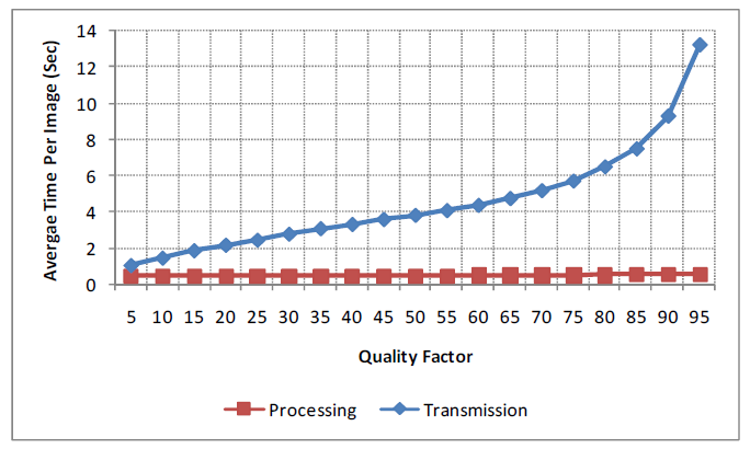%20waktu.png) 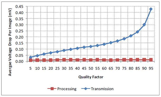%20drop%20tegangan.png) 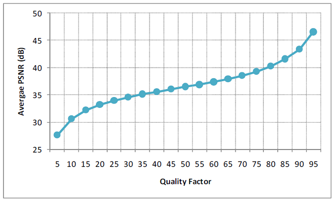%20PSNR.png) In another paper, Mowafi (2012) implements IJG and JPEG2000. Variation of the quality factor in IJG and Compression Ratio in JPEG2000 was done by finding the same file size in the two compression techniques. After that, the two compression techniques were compared by measuring the time for compression, the transmission time after compression, and the energy consumption of the bit rate. PSNR measurement of the two compression techniques is also done based on the size of the file. Finally, a simulation with a multi-hop sensor was carried out where time and energy consumption were the benchmarks for the two compression techniques. The parameters were obtained from previous single-hop research. The result is that the JPEG2000 excels in terms of PSNR, power consumption during transmission, and transmission time, but JPEG excels in terms of power consumption and compression time. The compression time consumption in JPEG is the least compared to other aspects, while the compression time consumption in JPEG2000 is the largest on the contrary, from the overall compression and transmission process. The research results can be seen in Figure 2.6. So it can be concluded that JPEG is more efficient on WSVN with short hops because it is economical on the compression side, does not require a long transmission line. If with long hops it is recommended to use JPEG2000 because it is more efficient on the transmission side. WSVN will be more optimal if various compression techniques are applied in order to be flexible to circumstances. 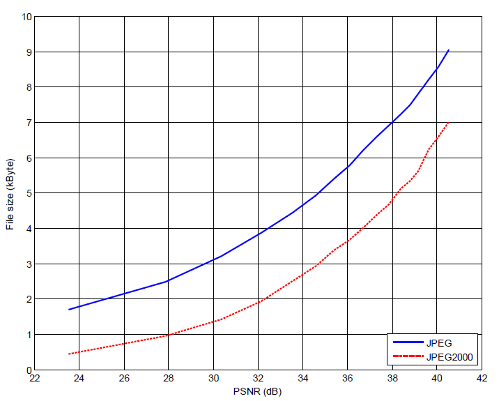%20PSNR.png) 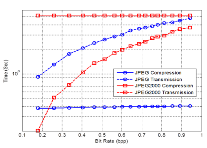%20Energi.png) 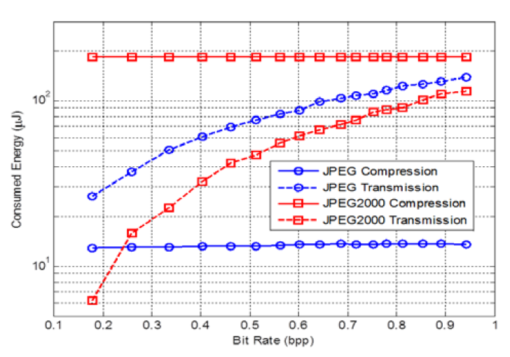%20Waktu.png) Pekhteryev's (2005) research in transmitting images on IEEE 802.15.4 and Zigbee networks are very similar to this study. Due to the very limited transmission capacity and the absence of fragmentation and reassembly features, the NWK layer is required to make an application with these features. The research is to observe the number of error sending images from sending 100 JPEG images and 100 JPEG2000 images on 1-hop and 2-hop networks as shown in Figure 2.7, the results can be seen in Figures 2.8 and 2.9. 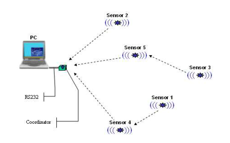 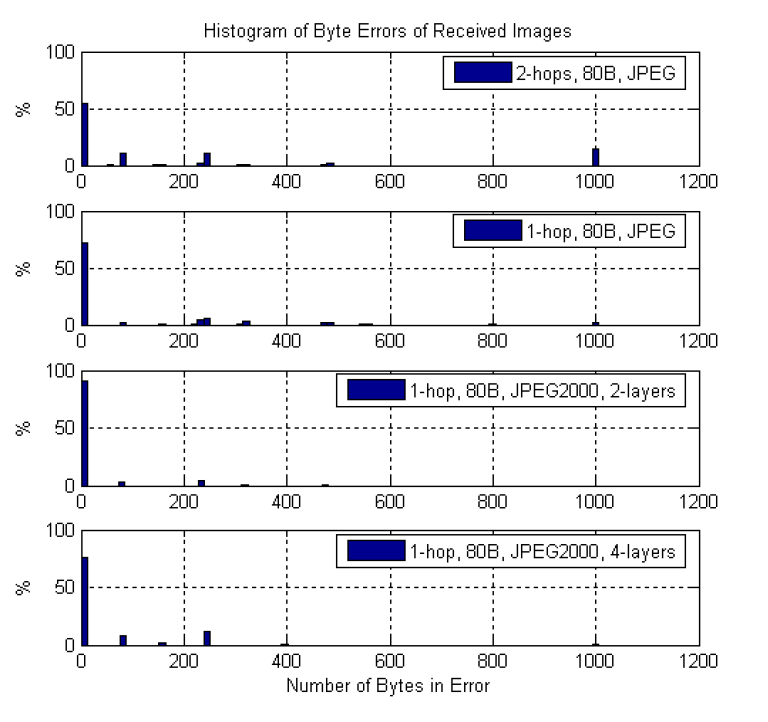 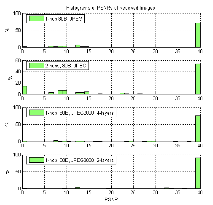 This study implements image transmission in the IEEE 802.15.4 Zigbee transmission as research by Pekhteryev (2005). The difference from this study is that Pekhteryev's (2005) study uses an M16C microcontroller and analyzes transmission errors more, whereas this study uses the Imote2 platform device and analyzes the energy efficiency of transmission. Furthermore, the image is compressed first using the JPEG2000 standard before transmission, such as Mowafi's research (2012). The difference between this study and Mowafi (2010, 2012) is the operating system used, Mowafi's research (2010, 2012) uses TinyOS while this research uses embedded Linux. In addition, there is no research (from the author's knowledge) that discusses the image transmission scheme on the IEEE 802.15.4 Zigbee WSVN, especially in the Imote2 Linux embedded system. The essence and the fundamental difference of this research from the others is that the image transmission program in C language and a schematic is made to function as a testbed in Imote2 Linux. 2.3 Electrical PowerElectric power mathematically defined as the electrical energy produced per time. P=dw/dt (2.1) Where: p = electrical power (watt) w = electrical energy (joule) t = time (second) Electric power can be formed by multiplying electric voltage and electric current. If the electric voltage is the average electrical energy per electric charge, and the electric current is the electric charge that flows every second, the multiplication of these two variables produces electric power. (Irwin, 1993). V=dw/dq, I=dq/dt, VI=(dw/dq)(dq/dt)=(dw/dt)=P (2.2) Dimana: V = electrical voltage (volt) q = electrical charge (coloumb) I = electric current (ampere) 2.4 IEEE 802.15.4 ZigBee StandardThis standard is a collaboration between IEEE (Institute of Electronic and Electrical Engineer) and ZigBee. IEEE focuses on developing standards at the lower layers, namely the PHY (Physical) layer and MAC (Media Access Control) or datalinklayer. Meanwhile, ZigBee focuses on developing the layer above it, to the application layer. The IEEE 802.15 standard is specifically for WPAN (Wireless Personal Area Network) with the aim of low power consumption, short range, and small device size. If 802.15.1 (bluetooth) is an intermediate standard, 802.15.3 is HR(high rate)-WPAN with high data rate, then 802.15.4 is LR(low rate)-WPAN with low data rate but low power consumption. While 802.15.2 is a standard for connecting between types of wireless devices (Ergen, 2004). 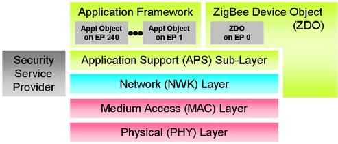 2.4.1 PHY LayerIs the lowest layer that regulates transmission. Symbol formation uses O-QPSK (Offset Quadriture Phase Shift Keying) modulation to reduce consumption in transmission. Operating frequency bands are divided into 27 channels based on DSSS (Direct Sequence Spread Spectrum) as shown in Figure 2.11. 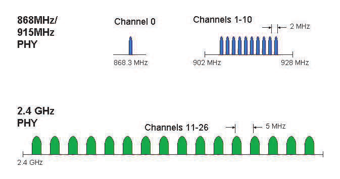 Channel 0 is at a frequency of 868.3 MHz with a data rate of 20 Kbps, channels 1-10 are at a frequency of 902 Mhz with a distance between channels of 2 MHz with a data rate of 40 Kbps, and channels 11-26 are at a frequency of 2.4 GHz with a distance between channels of 5 MHz with a data rate of 250 Kbps. The minimum sensitivity of channel is 0-10 -92dBm while channel 11-26 is 85 dBm (Ergen, 2004), the details can be seen in table 2.1. 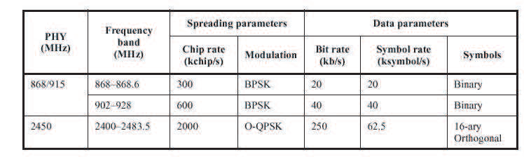 Features of the PHY layer (Ergen, 2004):
 2.4.2 MAC LayerMAC layer is the layer that regulates the flow of data from the PHY layer to the network layer and vice versa. A device can be either an FFD (Full Function Device) or an RFD (Reduced Function Device). An FFD can function as a PAN (Personal Area Network) coordinator, coordinator, or member. The MAC layer manages the following devices (Ergen, 2004):
2.4.3 Network LayerThe network layer manages the network, including the routing mechanism. In general, at this layer two algorithms are used, namely AODV (Ad Hoc On Demand Distance Vector) and Motorola's Cluster-Tree algorithm. (Ergen, 2004).
2.4.4 Application LayerThis layer consists of the application framework and application support (APS) sublayer. Application framework manages communication that connects end-users to the layer below the application. Meanwhile, the application support sublayer manages the relationship between the application framework and the network layer, specifically managing application profiles, clusters, and endpoints. An application profile describes a set of devices running on a specific application, for example application profiles for home automation systems and commercial, industrial and institutional settings. A device in an application profile communicates in a cluster, for example, in a home automation profile there is a cluster that regulates the lighting subsystem. While endpoints is a communication entity, which has been determined about the application that is running, for example a button on the remote control. The important thing about application support sublayer is binding, which here is interpreted as a link between endpoints, for example to turn on the light with a button on the remote. Binding can be direct or indirect. The direct connection between the remote and the light is direct binding. Indirect binding, there is a router between the remote and the light, usually there is a cluster library. There are commands in the cluster library that can be used together, you only need to add the cluster ID to the command, for example the on/off command needs to be added to the cluster ID for the target device (Daintree Network, 2006). Fragmentation and reassembly are not performed at the NWK layer, therefore the application layer must be developed for fragmentation and reassembly and adapted for image transmission (Pekhteryev, 2005). 2.5 Intel Mote 2 (Imote2)Imote2 is a platform on the WSN device developed by Intel Research in the platform X research section. This device is built with low power consumption, with a PXA271 XScale CPU processor, and is integrated in IEEE 802.15.4 ZigBee (Stanford, 2013). This processor (Intel Xscale processor PXA271) can operate at low voltages (0.85V) and frequencies of 13MHz to 104MHz. The frequency can be increased up to 416MHz by adjusting the voltage. In general, Imote2 consists of 4 parts as shown in Figure 2.21. 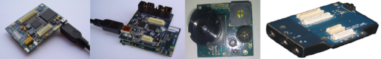 2.5.1 Radio Processor Board IPR2400IPR2400 specifications can be seen as follows (crossbow, 2007):
2.5.2 Interface Board IIB400IIB400 specifications can be seen as follows (crossbow, 2007):
2.5.3 Sensor Board IMB400IMB400 specifications can be seen as follows (crossbow, 2007):
2.5.4 Power Supply Board IBB2400IBB2400 specifications can be seen as follows (crossbow, 2007):
2.6 JPEG2000JPEG2000 is an image compression standard developed by JPEG (Joint Photographic Expert Group) around 2000 with the hope that this image compression standard based on DWT (Discrete Wavelet Transform) provides better quality than the pre-image compression standard developed in 1992, namely JPEG. which is based on DCT (Discrete Cosine Transform). The advantages of JPEG2000 with JPEG are as follows:
In general, the technicality of JPEG2000 image compression can be seen in Figure 2.22 and vice versa.  The JPEG2000 image compression standard is regulated in ISO/IEC 15444 which consists of 14 parts, the basic characteristics of the JPEG2000 are regulated in the first part, namely ISO/IEC 15444-1 core coding system. The encoding in JPEG2000 can be seen in Figure 2.23. 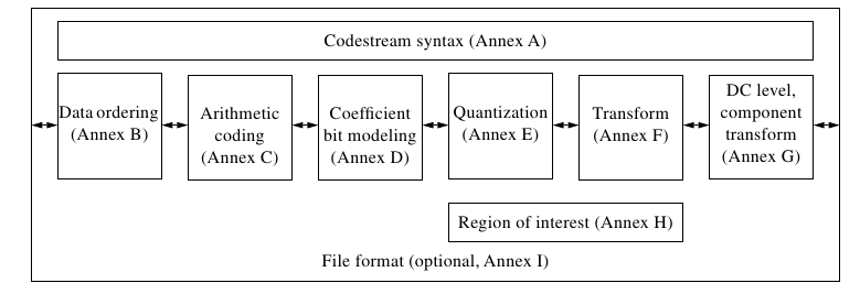 2.6.1 Codestream syntaxBefore DWT image can be done, it must be converted into signal. This is done in the syntax codestream. In this section, there is either a core header or a header tile. The header consists of several segment markers that contain minimal information about a component, for example tile size, ROI (Region of Interest), and quantization, which can be seen in Table 2.2 and Table 2.3 (Boliek, 2000). 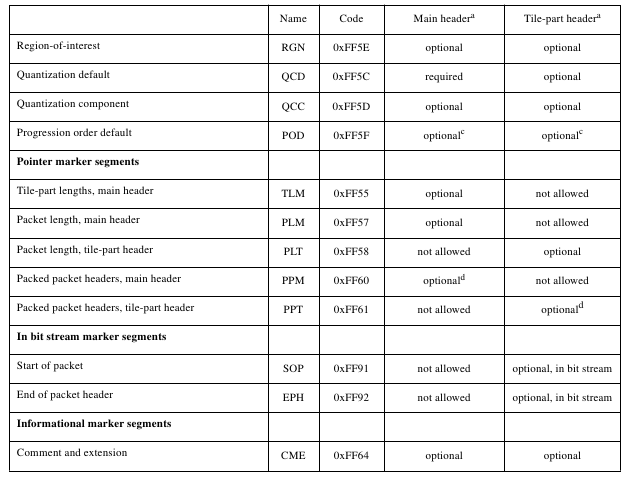 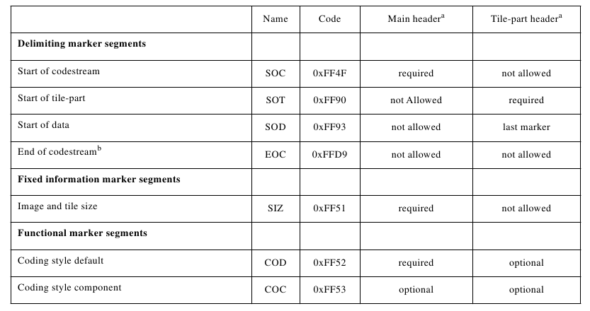 2.6.2 Data OrderingIn this section, an image is divided into several components. In this section, tiling is performed as in Figure 2.24, namely dividing the image into squares, so that coding does not have to be done on the entire image, coding can be done in a certain part, for example increasing the resolution can be done in a certain part, not necessarily the whole image. 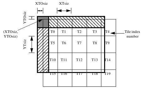 After that the tiles are divided into several resolutions and sub-bands, including the LL, LH, HL, and HH sub-bands as shown in Figure 2.25. Resolution is divided into precincts, and sub-band is divided into code-blocks. The data is distributed on 1 or more layers where the information content of each layer is stored in packages. The last is the progression order that allows multi-resolution, the level of resolution will increase along with sending data, in other words, there is no need to take all the data to display the image (Boliek, 2000). 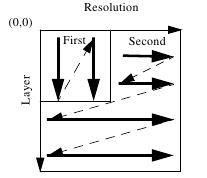 2.6.3 Arithmetic Entropy CodingAfter getting the coefficients, the next step is arithmetic entropy coding where information is represented in digital form. The JPEG2000 uses Elias entropy coding where a positive integer x is represented as 1 + floor(log(2)x). Because the image has been divided into several tiles, coding is performed on each tile (Boliek, 2000). 2.6.4 Coefficient Bit ModelingIn this section important or rare information appears filtered. Each coefficient in the sub-band has been divided into code blocks as shown in Figure 2.26. 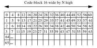 After that the code block is ready to enter coding passes. Coding passes consists of 3, namely (Boliek, 2000):
2.6.5 QuantizationQuantization is a process of rounding coefficients. In JPEG2000 formula 2.3 is used to find the stepsize then uses the 2.4 quantization formula (Boliek, 2000). ∆b=2Rb−εb(1+(μb/2)) (2.3) ∆b : stepsize Rb : dynamic range sub-band b εb : exponent μb : mantisa q(u,v)=sign(ab(u,v))(ab(u,v)/∆b) 2.4 2.6.6 TransformIn the JPEG2000 standard FDWT (Foward Discrete Wavelet Transform) is carried out on each tile. FDWT passes tile coefficient with low pass filter and high pass filter to get low pass coefficient and high pass coefficient. The first level of FDWT produces a sub-band LL (Low-Low) which consists of a vertical low pass coefficient and a horizontal low pass, LH (Low-High) which consists of a vertical low pass coefficient and a horizontal high pass, HL (High-Low) which consists of a coefficient vertical high pass and horizontal low pass, and HH (High-High) which consists of the coefficient of vertical high pass and horizontal high pass. The next level is carried out by FDWT on the LL sub-band, and the resulting new LL sub-band depends on the specified level as shown in Figure 2.27. The vertical low pass coefficient is obtained by applying the low pass filter to the tile vertically, while the horizontal low pass coefficient is obtained by applying the low pass filter to the tile horizontally and so on. On the decoder side, the IDWT (Inverse Discrete Wavelet Transform) process is carried out, which is the reverse process of FDWT (Boliek, 2000). 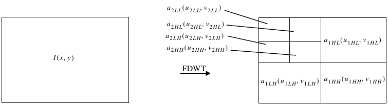 2.6.7 DC Level, Component TransformForward DC level shift is done before doing FDWT. After doing the forward DC level, a forward component transform can be performed to make compression more efficient, but this process may not be done as shown in Figure 2.28 (Boliek, 2000).  2.6.8 Region of InterestROI (Region of Interest) is part of the image that will be encoded on the codestream first with the aim of this section being given greater quality. The method used is Maxshift. Generally consists of 4 steps (Boliek, 2000).
2.7 Peak Signal to Noise RatioPSNR (Peak Signal to Noise Ratio) is a measure commonly used to measure the quality of the image that has been processed against the original. First, the error calculation for the image that has been processed with f (x,y) against the original image g (x,y) is carried out. After obtaining the MSE (Mean Square Error) value that will be used to find the PSNR value (Shi, 2007). e(x,y)=f(x,y)− g(x,y) (2.5) e : error f : processed image g : original image x : horizontal coordinate y : vertical coordinate MSE=(1/MN)ΣM-1x=0ΣN-1y=0e(x,y)2 (2.6) MSE : Mean Square Error M : horizontal dimensions of the image N : vertical dimensions of the image PSNRdB=10log10(2552/MSE)dB (2.7) PSNR : Peak Signal to Noise Ratio in decibel Chapter 3 Research Method3.1 Location and Time of ResearchObservation and data collection were carried out at the Communication Systems Laboratory, Department of Electrical Engineering, Faculty, Udayana University, Jimbaran and in the conference room, GDLN, Sudirman Campus, Udayana University. The research schedule plan starts from the end of May 2014 and must be completed before the end of November 2014, more details are in the Appendix. 3.2 Sources and Types of Research DataData sources can be grouped into 2 types:
The types of data are also grouped into 2 types:
3.3 Research Instruments and MaterialsThe research instrument can be seen in Table 3.1 - Table 3.5. The Imote2 JSVN device can be seen in Figure 2.10.
The research material is an image captured from the camera sensor of the WSVN Imote2 device on May 9, 2014 at the Communication Systems Laboratory, Department of Electrical Engineering, Udayana University with the Portable Pixelmap Graphic (.ppm) format, 480 x 640 pixel resolution in Figure 3.1, with a large file size. 921.6 KB, and IEEE 802.15.4 Zigbee-based transmission media. 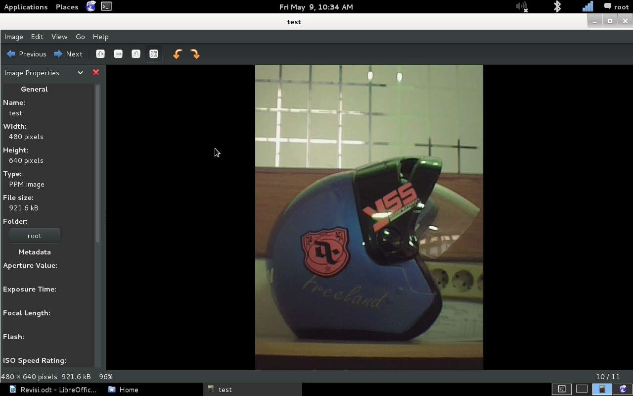 3.4 Research StagesOverall the research stage consists of 2 stages. The first stage is the procedure for implementing image transmission using IEEE 802.15.4 Zigbee transmission media on the Imote2 WSVN platform with the embedded Linux operating system. The mechanism for transmitting images is explained. The second stage is the testbed to test the performance of WSVN in image transmission. Performance is determined by the power consumption, the time required for transmission, and the amount of memory used. In general, the description of the stages can be seen in Figure 3.2. 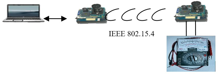 3.4.1 IEEE 802.15.4 Zigbee implementation for image transmissionRadio on Imote2 running Linux OS uses the Tosmac driver. Tosmac provides a script for transmit and receive which will be adjusted for image transmission. It can be seen as follows:
//************************************************************
//
// blocking.c
//
// Gefan Zhang
//
//*************************************************************
#include
#include
#include
#include
#include "tosmac.h"

void msg_init(TOS_Msg* pMsg)
{
   pMsg->length = 0;
   pMsg->fcfhi = 0;
   pMsg->fcflo = 0;
   pMsg->dsn = 0;
   pMsg->destpan = 0;
   pMsg->addr = 0;
   pMsg->type = 0;
   pMsg->group = 0;
   memset(pMsg->data, 0, TOSH_DATA_LENGTH);
   pMsg->strength = 0;
   pMsg->lqi = 0;
   pMsg->crc = 0;
   pMsg->ack = 0;
   pMsg->time = 0;
}

//--------------------- main -------------------------------

int main(int argc, char* argv[])
{
  int tosmac_dev;
  TOS_Msg recv_pkt;
  TOS_Msg send_pkt;
  // open as blocking mode
  tosmac_dev = open(TOSMAC_DEVICE, O_RDWR);
  if (tosmac_dev < 0)
  {
    fprintf(stderr, "Open error: %s\n", TOSMAC_DEVICE);
    return 1;
  }
  msg_init(&send_pkt);
  send_pkt.addr = 99;
//  memcpy(send_pkt.data, "DATA for test", 14);
  memcpy(send_pkt.data, "0000000000000", 14);
  send_pkt.length = 14;
  printf("User write to driver\n");
  write(tosmac_dev, (TOS_Msg*)&send_pkt, sizeof(TOS_Msg));
  // close device
  close (tosmac_dev);
  return 0;
}
//************************************************************
//
// blocking.c
//
// Gefan Zhang
//
//*************************************************************
#include
#include
#include
#include
#include "tosmac.h"
void msg_init(TOS_Msg* pMsg)
{
   pMsg->length = 0;
   pMsg->fcfhi = 0;
   pMsg->fcflo = 0;
   pMsg->dsn = 0;
   pMsg->destpan = 0;
   pMsg->addr = 0;
   pMsg->type = 0;
   pMsg->group = 0;
   memset(pMsg->data, 0, TOSH_DATA_LENGTH);
   pMsg->strength = 0;
   pMsg->crc = 0;
   pMsg->lqi = 0;
   pMsg->ack = 0;
   pMsg->time = 0;
}
//--------------------- main -------------------------------

int main(int argc, char* argv[])
{
  int tosmac_dev;
  TOS_Msg recv_pkt;
  TOS_Msg send_pkt;
  // open as blocking mode
  tosmac_dev = open(TOSMAC_DEVICE, O_RDWR);
  if (tosmac_dev < 0)
  {
    fprintf(stderr, "Open error: %s\n", TOSMAC_DEVICE);
    return 1;
  }
  printf("User read from driver:\n");
  read(tosmac_dev, &recv_pkt, sizeof(TOS_Msg));// != sizeof(TOS_Msg);
  printf("length is %d\n", recv_pkt.length);
  printf("data is %s\n", recv_pkt.data);
  // close device
  close (tosmac_dev);
  return 0;
}
3.4.2 TestbedThe testbed uses 2 WSVN Imote2 devices where one functions as a transmitter and the other functions as a receiver. At the transmitter, image capture is carried out with the camera sensor. At the transmitter, the image transmission to the receiver is carried out via wireless media based on IEEE 802.15.4 Zigbee. Image capture has been done in previous studies, therefore only observed in compression and transmission. There are 2 types of transmitted images, namely raw images from the capture of the IMB400 sensor and raw images processed based on the JPEG2000 standard with a ratio of 1, 5, and 10 where the ratio is the limiting of the channel capacity. A ratio of 5 means that the number of bits of the compressed image is limited to a maximum of 1/5 of the original number of bits, and a ratio of 10 means that it is limited to a maximum of 1/10 of the number of original bits. At the time of transmission, the measurement of power consumption, memory, and time is measured at the transmitter. Measurement of electric power consumption using a multimeter with the object of measurement is the battery on the power supply board (IBB2400). The measurement of electric power is done by measuring the voltage drop and current drop, in other words, the difference in the value of electric power before and after the research. In particular, it measures the consumption of electrical power starting from the command for transmission by the computer until the image is transmitted, as well as the time consumption. The measurement of consumption starts from giving commands by the computer, not from the start of image transmission because it also involves aspects of the operating system used, namely embedded Linux. The measurement result data is from one study. Memory based on the display from the terminal when transmitter access. The transmitted image is measured by PSNR. In general, the testbed can be seen in Figure 3.3, Scenarios will be described in the following sections: 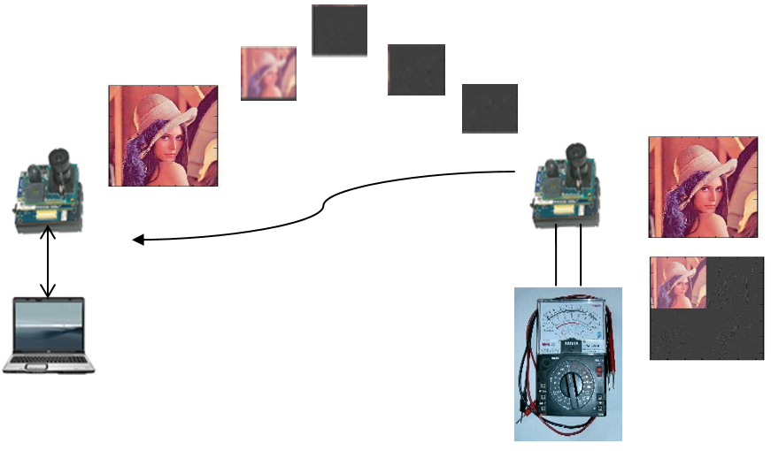
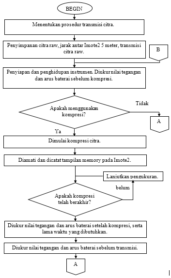
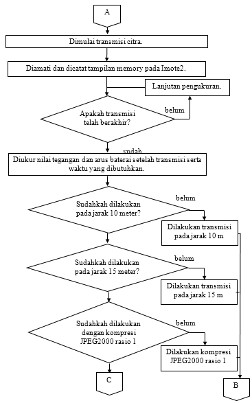
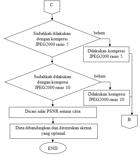
      3.5 Analysis FlowIn this section, the research stage will be described in a flowchart diagram in Figure 3.10, Figure 3.11, and Figure 3.12. The overall research is as follows:
   Chapter 4 DiscussionOverall, this chapter discusses the image transmission program, Imote2 Linux as a testbed of the compilation of transmission programs and JPEG2000 compression software to giving commands wirelessly to Imote2 which is the sender, and the final part of this chapter is displayed and analyzed the performance of the Imote2 device. From the research results, it turns out that doing compression before transmission is very helpful to lighten the burden of transmission, and interestingly, the compression process itself does not burden the device too much, so it is highly recommended to use compression. The point of this research is that Imote2 Linux can be used as a testbed. To summarize again, previous research has succeeded in embedding Linux into the JSVN Imote2 platform and transmitting random data, so in this study it is to transmit image data. The program code in section 3.4.1 is a program for sending character data of up to 28 bytes, then displayed on the screen. To send an image in the form of a file, the code must be modified so that the sender side can read and send the file, and on the receiving side can receive and save the file (not limited to being displayed on the screen), it must also be able to transmit files of more than 28 bytes. The process for enabling Imote2 Linux to function as a testbed is summarized in Figure 4.1. First, making program code, more fully discussed in section 4.1. Then the program is compiled in section 4.2 and section 4.3, and embeded into Imote2, illustration can be seen in Figure 4.2. Finally, Imote2 is configured to be able to receive commands via radio, in other words, after the transmitter is turned on, ready to receive commands, it can be illustrated in Figure 4.3. Commands can be in the form of compressing, or transmitting images as illustrated in Figure 4.4. This is done because the transmitter is powered by batteries (without cables), so communication is only available via radio. 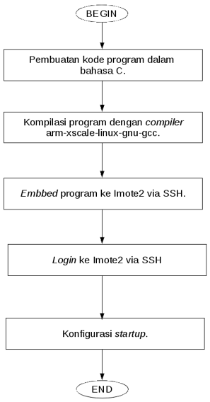 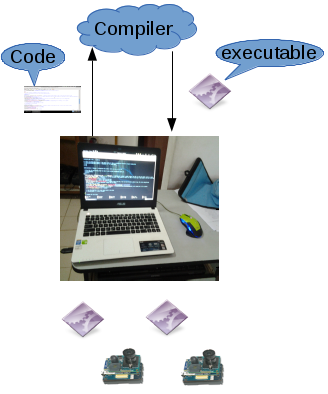 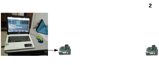 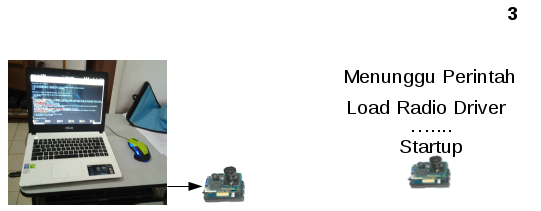 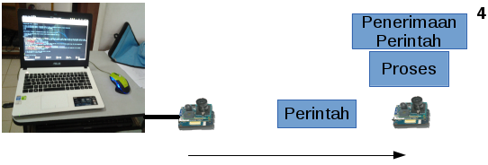 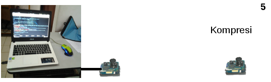 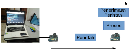 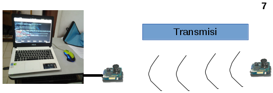 4.1 Transmission ProgramRadio transmission on Imote2. In the previous study described in section 2.1, using the driver from Tosmac to run the radio on Imote2 Linux, here still use the same driver. For transmission, two programs are needed, namely the program for sending and receiving. Both programs are written in C language. Specifically, this research follows the provisions of the tosmac header, namely the maximum data payload sent is 28 bytes. Overall on the sender side reads the image file to be sent, the receiver will create a new file and write the received data to the file. The delivery is done in stages by breaking 28 bytes of each tile (not all at once). 4.2 Sending ProgramThe following syntax shows a sending program with the file name "send_file_advance.c" which was carried out in this study and is described as follows: 1 //************************************************************ 2 // 3 // blocking.c 4 // 5 // Gefan Zhang 6 // 7 //************************************************************* 8 // Modified by : Fajar Purnama Lines 1 - 8 are comments containing information about the programmer and the modifier. Comments can be marked with "//" or begin with "/ *" and end with "* /" (which is not bold). Line 5 is the first author of the program, while line 8 is the name of the author who modified the program. 9 #include 10 #include 11 #include 12 #include 13 #include Lines 9 - 13 indicate the header used in this program, the header contains the code definition used. To use the header, you can use the character "#", this character indicates the script required by the program. On line 9 there is “stdio.h†which is the basic header for all C language programs which defines the “printf†command for displaying to the screen, “while†for looping, arithmetic operations, and many others. Line 10 "fcntl.h" defines the command "open" to open a file and "close" to close and "create" to create, line 11 "unistd.h" defines the command "read" to read the file and "write" to write data to file, and line 13 "tosmac.h" sets the variable in the tosmac (radio) driver.
14 void msg_init(TOS_Msg* pMsg)
15 {
16 pMsg->length = 0;
17 pMsg->fcfhi = 0;
18 pMsg->fcflo = 0;
19 pMsg->dsn = 0;
20 pMsg->destpan = 0;
21 pMsg->addr = 0;
22 pMsg->type = 0;
23 pMsg->group = 0;
24 memset(pMsg->data, 0, TOSH_DATA_LENGTH); // 28 bytes usually
25 pMsg->strength = 0;
26 pMsg->lqi = 0;
27 pMsg->crc = 0;
28 pMsg->ack = 0;
29 pMsg->time = 0;
30 }
Lines 14 - 30 are written in the form of the function "msg_init" which is a function to initialize the package variables such as address, group, and payload contained in the header "tosmac.h" for transmission. Inti program “int main†dimulai dari baris 32.
31 //---Main-Program---//
32 int main(int argc, const char *argv[]){
33 // Check Error
34 if(argv[1]==NULL){
35 printf("Usage: ./send_file [file], example: ./send_file_advance image.ppm");
36 return 1;
37 }
38 //sleep(10); //pause for 10 sec (give time for receiver to prepare) cross this out if not needed
39 // Declaration
40 int tosmac_dev, file, file_size, h, i, j, k;
41 //char *packet;
42 TOS_Msg recv_pkt;
43 TOS_Msg send_pkt;
44 // open as blocking mode
45 tosmac_dev = open(TOSMAC_DEVICE, O_RDWR);
46 if (tosmac_dev < 0)
47 {
48 fprintf(stderr, "Open error: %s\n", TOSMAC_DEVICE);
49
50 return 1;
51 }
52 // open file to be send
53 file = open(argv[1], O_RDWR); // open file
54 file_size = lseek(file,0,SEEK_END); // calculate filesize by going to final byte of file using lseek function from fcntl.h
55 lseek(file,0,SEEK_SET); // return to start of file
56 msg_init(&send_pkt);
57 send_pkt.addr = 99;  // Address
58 h = file_size/TOSH_DATA_LENGTH; // How much packet or times of transmission should be prepared (using div)
59 i = file_size%TOSH_DATA_LENGTH; // Remainder of "h" (using mod)
60 j = 0;
61 k = 0;
Lines 33 - 37 contain error checks if the command entered does not match, lines 39 - 43 are part of the variable declaration, lines 44 - 51 open the radio, lines 52 - 55 open the file, and lines 56 - 61 specify packets. On line 32 "int main" there is "int argc, int argv []" so that the program can be executed by selecting the desired file "./send_file_advance argv [1]", as defined on line 53 "file = open (argv [1 ], O_RDWR) â€. If there is no input, it will show how to use the program on line 35, namely "./send_file_advance file" which is set in the statement "if (argv [1] == NULL)" line 34, and line 36 "return 1" to provide an error code on the program if the input matches the statement line 34. Line 45 "tosmac_dev = open (TOSMAC_DEVICE, O_RDWR)" is to open the radio where "TOSMAC_DEVICE" is "/dev/tosmac" as defined in "tosmac.h", "O_RDWR" so that files opened, read & write, can be seen in "fcntl.h". Line 55 "file_size = lseek (file, 0, SEEK_END)" to find the file size by going to the last bit of the file to return it to the initial bit with the code "lseek (file, 0, SEEK_SET)". Defined packets to be sent are "TOS_Msg send_pkt" (line 42) and received "TOS_Msg recv_pkt" (line 43), where "TOS_Msg" is the packet structure defined in "tosmac.h". Line 57 "send_pkt.addr = 99" specifies that the address of the sender is 99. Line 58 "h" is the number of packets by dividing the file size by the maximum data payload "TOSH_DATA_LENGTH", here is 28, while the value "i" (line 59) is the remainder of the division of "h" which is the last byte to be sent.
62 while(j+1>>>> send_pkt.data
75 send_pkt.group = 7; // Group identifier, modify this as wished
76 // writing packet to device
77 printf("User writing %d bytes to driver\n", TOSH_DATA_LENGTH);
78 // verbose
79 write(tosmac_dev, (TOS_Msg*)&send_pkt, sizeof(TOS_Msg));
80 // writing to device, (TOS_Msg*)&send_pkt >>>>> tosmac_dev, & it's a pointer
81 k += TOSH_DATA_LENGTH; // accumulative payload sent
82 printf("%d bytes written\n", k); // verbose
83 // use this function if for some reason need to slow down
84 // usleep(30000); // in micro seconds
85 }
86 // Sending the last bytes
87 read(tosmac_dev, (TOS_Msg*)&recv_pkt, sizeof(TOS_Msg));
88 // Waiting for receiver to send a packet (for ACK), it will wait
89 until receiver is ready
90 read(file,send_pkt.data,i); // i = remainder
91 printf("User writing %d bytes to driver\n", i); // verbose
92 write(tosmac_dev, (TOS_Msg*)&send_pkt, i); // final sending
93 k += i; // accumulative payload sent
94 memcpy(send_pkt.data,"0S0T1O1P0",9);
95 write(tosmac_dev, (TOS_Msg*)&send_pkt, 9);
96 printf("%d bytes written, FINISH!!\n", k); // verbose
Lines 62 - 85 are the process transmission and lines 85 - 96 are the last transmissions. The transmission process is contained in line 62 of the while loop, where files are sent every 28 bytes. Looping will stop if "j" reaches the value "h" (number of packets). Before transmission awaits information from the receiver containing the number of packets received on line 68 "read (tosmac_dev, (TOS_Msg *) & recv_pkt, sizeof (TOS_Msg))" (this code will read data received by radio "tosmac_dev" of "sizeof (TOS_Msg) "Which is then written to the pointer "&recv_pkt"). The value contained in “recv_pkt†will be entered into “j†(line 70). The arithmetic operation on “k†(line 72) converts the number of packets to the number of bytes received. After that it will go to the next byte which will be sent on line 73 "lseek (file, k, SEEK_SET)". Then On line 75, sizeof (TOS_Msg)) "(this code will write "&send_pkt "of" sizeof (TOS_Msg) "to" tosmac_dev"). After the while loop is sending the last byte "i" which is the remainder of the division of "j", the last one will send the code "0S0T1O1P0" to the receiver to notify that the transmission has ended. 97 //close device 98 close(tosmac_dev); 99 close(file); 100 return 0; 101 } Lines 97 - 101 radio and file closings and the end of the program, the code "close" to close the file defined in "fcntl.h". 4.1.2 Receiving ProgramThe following syntax shows the receiving program with the file name "recv_file_advance.c" which was carried out in the study and overall the receiving program is similar to the sending program, in other words only a slight difference can be explained as follows: 1 //************************************************************ 2 // 3 // blocking.c 4 // 5 // Gefan Zhang 6 // 7 //************************************************************* 8 // Modified by : Fajar Purnama Lines 1 - 8 are comments containing information about the programmer and the modifier. 9 #include 10 #include 11 #include 12 #include 13 #include Lines 9 - 13 indicate the header used in this program, the header contains the code definition used.
14 void msg_init(TOS_Msg* pMsg)
15 {
16 pMsg->length = 0;
17 pMsg->fcfhi = 0;
18 pMsg->fcflo = 0;
19 pMsg->dsn = 0;
20 pMsg->destpan = 0;
21 pMsg->addr = 0;
22 pMsg->type = 0;
23 pMsg->group = 0;
24 memset(pMsg->data, 0, TOSH_DATA_LENGTH); // 28 bytes usually
25 pMsg->strength = 0;
26 pMsg->lqi = 0;
27 pMsg->crc = 0;
28 pMsg->ack = 0;
29 pMsg->time = 0;
30 }
Lines 14 - 30 are functions for initializing the variables in the packet to be transmitted. The core of the program starts at line 32.
31 //--------------------- main -------------------------------
32 int main(int argc, const char *argv[]) {
33 // Check Error
34 if(argv[1]==NULL){
35 printf("Usage: ./recv_file [file], example: ./recv_file_advance image.ppm");
36 return 1;
37 }
Lines 33 - 37 contain error checks if the command entered does not match. 38 // Declaration 39 int tosmac_dev, file, i; 40 TOS_Msg recv_pkt; 41 TOS_Msg send_pkt; Lines 38 - 41 are part of the variable declaration.
42 // open as blocking mode
43 tosmac_dev = open(TOSMAC_DEVICE, O_RDWR); // TOSMAC_DEVICE = /dev/tosmac, O_RDWR = Open as Read & Write
44 // Check Error
45 if (tosmac_dev < 0)
46 {
47 fprintf(stderr, "Open error: %s\n", TOSMAC_DEVICE);
48
49 return 1;
50
51 }
Lines 42 - 49 open the radio.
50 // file
51 file = open(argv[1], O_RDWR);
52 // Check Error
53 if(file<0){
54 creat(argv[1], O_RDWR); // create empty file, argv[1] if no file exist: user input (./recv_file argv[1])
55 file = open(argv[1], O_RDWR); // Open created file
56 }
Lines 50 - 56 open the file in this section if no file is found it will create a new file with the "creat" function line 54.
57 // receving file
58 printf("User read from driver:\n");
59 // receive 28 bytes of file for infinity
60 while(1){
61 // Seek to end of file to continue receive (this feature allows continueable download)
62 i = lseek(file,0,SEEK_END);
63 send_pkt.data[1] = (i/TOSH_DATA_LENGTH)-3000; // Since the max value of data type is 3000 we start from -3000, so we could put a number up to 6000, This feature request tells the transmitter how much bytes already received so the transmitter will sinchronize.
64 write(tosmac_dev, (TOS_Msg*)&send_pkt, sizeof(TOS_Msg)); // sending i in send_pkt.data[1]
65 alarm(2); // 2  seconds timeout
66 read(tosmac_dev, (TOS_Msg*)&recv_pkt, sizeof(TOS_Msg)); // Read receive file from Tosmac Device, Pause if device == NULL, !=sizeof(TOS_Msg)
67 // Stop code, break infinite while loop if this code is received, send application should send this string to tell if transmission finish
68 if(strncmp(recv_pkt.data,"0S0T1O1P0",9)==0){
69 break;
70 }
71 // Use group as identifier, so it will not process packet if it is not on this group
72 if(recv_pkt.group!=7){
73 continue; // it will ignore next code and restart while loop
74 }
75 // Verbose, shows accumulative received number of bytes
76 printf("Receiving %d bytes of data\n", recv_pkt.length);
77 i += recv_pkt.length; // Equal to i = i + recv_pkt.length
78 printf("Received %d bytes\n", i);
79 // Writing received 28 bytes to file that had just been created
80 write(file, recv_pkt.data, recv_pkt.length); // write will automatically go to last byte order of file
81 }
Lines 60 - 81 represent the transmission process. In the process of transmitting in an infinite while loop, initially read the number of bytes that have been received by the file (file size) on line 62 "lseek (file, 0, SEEK_END)" and at the same time go to the end of the file. On line 63 the file size is entered into "send_pkt.data [1]" and on line 64 it is sent to the transmitter to tell which bytes should be sent. In this program the value starts from -3000 in order to determine a larger value because the maximum value is approximately 3000 while the value that needs to be sent is more than 3000. To do this there needs to be a change to "tosmac.h" in the packet definition section in the section . For this program the data type "data" changes from "s8" to "s16", the change is to increase the number of bits used. If this is set the maximum value in "send_pkt.data [1]" is only below 1000. All this is done so that the transmission can be resumed if it breaks and suppresses errors. This program is filled with "alarm (2)" on line 65, meaning the program will stop (time out) if 1 while loop exceeds 2 seconds. If this occurs the transmission can be resumed by running the program again showing the same file. Another difference is on line 72 "if (send_pkt.group =! 7) {continue;}" which means if the packet received is not a group 7 to ignore and continue to the next loop. In line 68 "if (strncmp (recv_pkt.data," 0S0T1O1P0 ", 9) == 0) {break;}" means if the received string is "0S0T1O1P0" and the number of characters is "9" then break the while loop, it is determined that the string this is a sign that the transmission has ended.
82 printf("FINISH!!");
83 // closing device and file
84 close (tosmac_dev);
85 close(file);
86 return 0;
87 }
Lines 82 - 87 close radio and file and end of program. 4.2 Openjpeg CompilationThis section contains ways to compile the Openjpeg-1.5.1 software onto Imote2-Linux, in order to make the compression software available on the device. The compiler used is linux-gcc-4.1.2-arm-xscale-linux-gnu-glibc-2.3.3 with dependencies lcms2, libpng, and zlib, for here lcms2-2.6, libpng-1.2.51, and zlib-1.2.8. The source obtained is compressed in gunzip tape archive format. The following command to extract the compressed file contents: Lines 60 - 81 represent the transmission process. In the process of transmitting in an infinite while loop, initially read the number of bytes that have been received by the file (file size) on line 62 "lseek (file, 0, SEEK_END)" and at the same time go to the end of the file. On line 63 the file size is entered into "send_pkt.data [1]" and on line 64 it is sent to the transmitter to tell which bytes should be sent. In this program the value starts from -3000 in order to determine a larger value because the maximum value is approximately 3000 while the value that needs to be sent is more than 3000. To do this there needs to be a change to "tosmac.h" in the packet definition section in the section. For this program the data type "data" changes from "s8" to "s16", the change is to increase the number of bits used. If this is set the maximum value in "send_pkt.data [1]" is only below 1000. All this is done so that the transmission can be resumed if it breaks and suppresses errors. This program is filled with "alarm (2)" on line 65, meaning the program will stop (time out) if 1 while loop exceeds 2 seconds. If this occurs the transmission can be resumed by running the program again showing the same file. Another difference is on line 72 "if (send_pkt.group =! 7) {continue;}" which means if the packet received is not a group 7 to ignore and continue to the next loop. In line 68 "if (strncmp (recv_pkt.data," 0S0T1O1P0 ", 9) == 0) {break;}" means if the received string is "0S0T1O1P0" and the number of characters is "9" then break the while loop, it is determined that the string this is a sign that the transmission has ended. tar xfv linux-gcc-4.1.2-arm-xscale-linux-gnu-glibc-2.3.3.tgz tar xfv openjpeg-1.5.1.tar.gz tar xfv zlib-1.2.8.tar.gz tar xfv lcms2-2.6.tar.gz tar xfv libpng-1.2.51.tar.gz The following command adds the location of the compiler executable file: export PATH=/[lokasi folder]/arm-xscale-Linux-gnu/bin/:$PATH The first additional dependencies requested are lcms2. cd /[lokasi folder]/lcms2-2.6 export CROSS-PREFIX=/[lokasi folder]/arm-xscale-linux-gnu/arm-xscale-linux-gnu/ ./configure --prefix=/[lokasi folder]/arm-xscale-Linux-gnu/arm-xscale-Linux-gnu/ --host=arm-xscale-linux-gnu make && make install Command "cd" to go to the folder, "export" to assign a value to a variable, here "CROSS-PREFIX" is defined in the "configure" file on zlib, if compiled for cross-compiler it is given the value of the cross-compiler location. In the file "configure" there is a series of configuration, when executed will be created "Makefile" to compile as needed. Command "--prefix" to add the installation location. Command "make" to compile based on files "Makefile" and "make install" to put the compilation into place according to "--prefix". Next compile zlib for the compiler: cd /[lokasi folder]/zlib-1.2.8 CC=arm-xscale-linux-gnu-gcc prefix=/[lokasi folder]/arm-xscale-Linux-gnu/arm-xscale-Linux-gnu/ CFLAGS=â€-04†./configure --shared make && make install In this research, we need the command "--shared" so that it can be detected by "libpng" during configuration. After that compile libpng: cd /[lokasi folder]/libpng-1.2.51 ./configure --prefix=/[lokasi folder]/arm-xscale-linux-gnu/arm-xscale-linux-gnu/ --host=arm-xscale-linux-gnu make && make install Command "cd" to go to the folder, "export" to assign a value to a variable, here "CROSS-PREFIX" is defined in the "configure" file on zlib, if compiled for cross-compiler it is given the value of the cross-compiler location. In the file "configure" there is a series of configuration, when executed will be created "Makefile" to compile as needed. Command "--prefix" to add the installation location. Command "make" to compile based on files "Makefile" and "make install" to put the compilation into place according to "--prefix". Next compile zlib for the compiler: cd /[lokasi folder]/zlib-1.2.8 CC=arm-xscale-linux-gnu-gcc prefix=/[lokasi folder]/arm-xscale-Linux-gnu/arm-xscale-Linux-gnu/ CFLAGS=â€-04†./configure --shared make && make install In this research, we need the command "--shared" so that it can be detected by "libpng" during configuration. After that compile libpng: cd /[lokasi folder]/libpng-1.2.51 ./configure --prefix=/[lokasi folder]/arm-xscale-linux-gnu/arm-xscale-linux-gnu/ --host=arm-xscale-linux-gnu make && make install Based on the file "configure" "--host" determines the type of compilation platform, here is "arm-xscale-linux-gnu", it is necessary to "export" the cross-compiler executable location at the beginning of this section. Lastly is the Openjpeg compilation: cd openjpeg-1.5.1 ./configure --prefix=/[lokasi folder]/[lokasi folder bebas]/ --host=arm-xscale-Linux-gnu --enable-jpwl --enable-debug --disable-tiff make && make install 4.3 Testbed ImplementationOverall, this section contains the transmission process for this study. Initially including the transmission program and Openjpeg so that in essence the device can transmit on a battery or without being connected to a computer. 4.4 Command ProgramHere there are additional programs, apart from using the "recv" program, 2 additional programs are needed, namely a program to send commands and a program to receive commands. The program sending the command "send_command.c" is as follows:
1 //************************************************************
2 //
3 // blocking.c
4 //
5 // Gefan Zhang
6 //
7 //*************************************************************
8 // Modified by Fajar Purnama
9 /* Only Difference from original send.c is an addition of arguement (argc, argv) we could send any message we want without changing its source code for example sending hello message just type ./send_command hello */
10 #include
11 #include
12 #include
13 #include
14 #include
15 void msg_init(TOS_Msg* pMsg) {
16 pMsg->length = 0;
17 pMsg->fcfhi = 0;
18 pMsg->fcflo = 0;
19 pMsg->dsn = 0;
20 pMsg->destpan = 0;
21 pMsg->addr = 0;
22 pMsg->type = 0;
23 pMsg->group = 0;
24 memset(pMsg->data, 0, TOSH_DATA_LENGTH);
25 pMsg->strength = 0;
26 pMsg->lqi = 0;
27 pMsg->crc = 0;
28 pMsg->ack = 0;
29 pMsg->time = 0;
30 }
31 //--------------------- main -------------------------------
32 int main(int argc, const char *argv[]) {
33 if(argv[1]==NULL){
34 printf("Usage: ./send_command [message], example ./send_command reboot, ./send_command hello\n");
35 return 1;
36 }
37 int tosmac_dev;
38 TOS_Msg recv_pkt;
39 TOS_Msg send_pkt;
40 // open as blocking mode
41 tosmac_dev = open(TOSMAC_DEVICE, O_RDWR);
42 if (tosmac_dev < 0)
43 {
44 fprintf(stderr, "Open error: %s\n", TOSMAC_DEVICE);
45 return 1;
46 }
47 msg_init(&send_pkt);
48 send_pkt.addr = 99;
49 memcpy(send_pkt.data, argv[1], TOSH_DATA_LENGTH);
50 send_pkt.length = TOSH_DATA_LENGTH;
51 printf("User write to driver\n");
52 write(tosmac_dev, (TOS_Msg*)&send_pkt, sizeof(TOS_Msg));
53close(tosmac_dev);
54 return 0;
55 }
The entire description of the command-sending program is the same as that of the transmission program. In particular, what is different in this program is on line 49 where the characters to be written to "send_pkt.data", namely "argv [1]" will be sent. This program is limited to sending characters up to 28 bytes. Here is the program for receiving the command "recv_command.c":
1 //************************************************************
2 //
3 // blocking.c
4 //
5 // Gefan Zhang
6 //
7 //*************************************************************
8 // Modified by Fajar Purnama
9 /* The only difference is system() function is added from stdlib.h so the message received will be proccess as a command with this code still limited to 28 bytes. Example of message receive is recv_pkt.data = "reboot", it will be system("reboot"), and it will reboot the system */
10 #include
11 #include
12 #include
13 #include
14 #include
15 #include
16 void msg_init(TOS_Msg* pMsg)
17 {
18 pMsg->length = 0;
19 pMsg->fcfhi = 0;
20 pMsg->fcflo = 0;
21 pMsg->dsn = 0;
22 pMsg->destpan = 0;
23 pMsg->addr = 0;
24 pMsg->type = 0;
25 pMsg->group = 0;
26 memset(pMsg->data, 0, TOSH_DATA_LENGTH);
27 pMsg->strength = 0;
28 pMsg->crc = 0;
29 pMsg->lqi = 0;
30 pMsg->ack = 0;
31 pMsg->time = 0;
32 }
33 //--------------------- main -------------------------------
34 int main(int argc, char* argv[])
35 {
36 int tosmac_dev;
37 TOS_Msg recv_pkt;
38 TOS_Msg send_pkt;
39 // open as blocking mode
40 tosmac_dev = open(TOSMAC_DEVICE, O_RDWR);
41 if (tosmac_dev < 0)
42 {
43 fprintf(stderr, "Open error: %s\n", TOSMAC_DEVICE);
44 return 1;
45 }
46 printf("User read from driver:\n");
47 read(tosmac_dev, &recv_pkt, sizeof(TOS_Msg));// != sizeof(TOS_Msg);
48 printf("data is %s\n", recv_pkt.data);
49 system(recv_pkt.data);// Process recv_pkt.data as a command in terminal
50 // close device
51 close (tosmac_dev);
52 return 0;
53 }
The overall description of the receiving program is the same as the description of the transmission program. In particular, what is different about this program is that on line 49 the received characters contained in "recv_pkt.data" will be treated as commands. This is made possible by the “system†function defined in “stdlib.hâ€. 4.3.2 Program PlacementAfter the program code is finished, the code is compiled using “arm-xscale-linux-gnu-gccâ€. export PATH=/[lokasi folder]/arm-xscale-Linux-gnu/bin/:$PATH (jika belum) cd /[lokasi folder program] arm-xscale-linux-gnu-gcc -Wall send.c -o send arm-xscale-linux-gnu-gcc -Wall recv.c -o recv arm-xscale-linux-gnu-gcc -Wall send_command.c -o send_command arm-xscale-linux-gnu-gcc -Wall recv_command.c -o recv_command arm-xscale-linux-gnu-gcc -Wall send_file_advance.c -o send_file_advance arm-xscale-linux-gnu-gcc -Wall recv_file_advance.c -o recv_file_advance Then placed in Imote2 in the directory "/root/transmit". The receiver is connected on USB0 with an IP address on the computer 192.168.98.100 and on Imote2 192.168.98.101. The transmitter is connected on USB1 with an IP address on the computer 192.168.99.100 and on Imote2 192.168.99.102. The connection between Imote2 uses SSH (secure shell) which has been prepared in previous studies as described in Chapter 2 section 2.1. Before placing the directory first. ssh 192.168.98.101 mkdir /root/transmit && mkdir /root/command && mkdir /root/image quit && exit ssh 192.168.99.102 mkdir /root/transmit && mkdir /root/command && mkdir /root/image quit && exit Command "mkdir" (make directory) to create a new folder. For this research, the raw image (Figure 3.1) is contained in the directory "/root/image" under the name "1.ppm". When the directory is ready then the program is entered, as well as the compiled Openjpeg. cd /[lokasi program] scp * [email protected]:transmit/ && scp * [email protected]:transmit/ cd /[lokasi folder openjpeg] scp -r [folder openjpeg] [email protected]: scp -r [folder openjpeg] [email protected]: SCP is a command to copy data via SSH, "*" indicates all files in that folder, "-r" to copy a directory. Next, the compiled Openjpeg will be placed in the appropriate directory. ssh 192.168.99.102 cd /[lokasi folder openjpeg] cd bin && mv * /bin cd ../include && mkdir /usr/include && mv * /usr/include cd ../lib && mv * /lib cd ../share && mv man /usr/share && mv /doc/* /usr/share/doc quit && exit ssh 192.168.98.101 cd /[openjpeg folder location] cd bin && mv * /bin cd ../include && mkdir /usr/include && mv * /usr/include cd ../lib && mv * /lib cd ../share && mv man /usr/share && mv /doc/* /usr/share/doc quit && exit To facilitate transmission several commands are prepared in the form of a file as follows:
Files from the table above will be placed in the directory “/root/commandâ€. cd /[command file location] scp * [email protected]:command/ scp * [email protected]:command/ 4.3.3 Startup ConfigurationThe final step for implementing the testbed is for the two Imote2 to be powered on to prepare the Tosmac driver for the radio and the transmitter when turned on is always ready to receive commands from the receiver. This study uses a radio that has been prepared in previous studies. To do this put 2 startup files in "/etc/rc2.d/". File "S12loadtosmac" for radio and file "S14infloop" for receiving commands continuously. Figure 4.1 is an example when sending a "poweroff" command to turn off the device and Figure 4.2 is an example of transmission. #!/bin/sh insmod /lib/modules/2.6.29.1_r1.1/kernel/arch/arm/mach-pxa/ssp.ko insmod /lib/modules/2.6.29.1_r1.1/kernel/drivers/tosmac/tos_mac.ko mknod /dev/tosmac c 240 0 while (true) do /root/transmit/recv_command Done 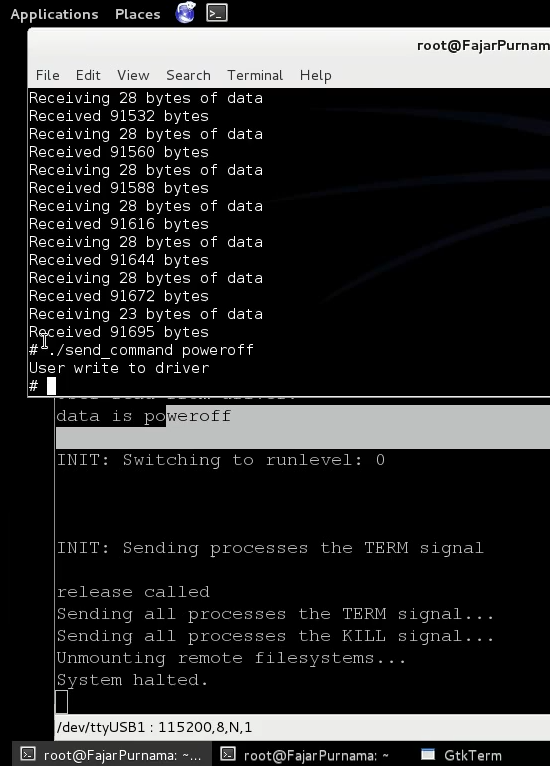 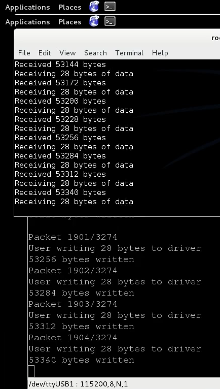 4.3.4 Testbed UsageTo perform uncompressed and compressed image transmission as follows: /root/transmit/send_command /root/command/A (raw image transmission) /root/transmit/recv_file_advance /root/image/[output image name].ppm /root/transmit/send_command /root/command/B (rasio 1 compression) /root/transmit/recv (wait for compression completion notification) /root/transmit/send_command /root/command/C (rasio 1 image transmission) /root/transmit/recv_file_advance /root/image/[output image name].j2k /root/transmit/send_command /root/command/D (kompresi rasio 5) /root/transmit/recv (wait for compression completion notification) /root/transmit/send_command /root/command/E (rasio 5 image transmission) /root/transmit/recv_file_advance /root/image/[output image name].j2k /root/transmit/send_command /root/command/F (rasio 10 image transmission) /root/transmit/recv (wait for compression completion notification) /root/transmit/send_command /root/command/G(transmisi citra rasio 10) /root/transmit/recv_file_advance /root/image/[output image name].j2k PSNR measurement using ImageMagick software. An image compressed with .j2k format is returned to the .ppm format with the original file size. The commands are as follows: j2k_to_image -i [image .j2k] -o [image name .ppm] compare -metric PSNR [original image] [compared image] [image output measurement] Memory can be seen while the application is running with the command: ps (can be seen the application process number) cat /proc/[application proccess number]/status 4.4 Data AnalysisIn this section we will analyze the results of research data in the form of consumption of electrical power, memory, and time in each transmission process, and also display the PSNR value of the image that has been sent. If we summarize again, the transmission process includes uncompressed and compressed image transmission based on the JPEG2000 standard with OpenJPEG 1.5.2 software ratios 1, 5, and 10, carried out at a distance of 5m, 10m, and 15m. 4.4.1 Electric Power ConsumptionOverall, the results of the research data indicate that compression has a strong effect on transmission. To get the details of the electric power consumption, this study carried out the transmission process at a distance of 5 meters, 10 meters, and 15 meters respectively. 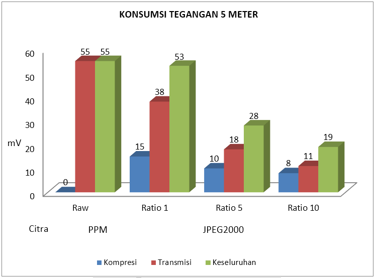 Figure 4.7 shows the power consumption of the transmission line at a distance of 5 meters. The stress consumption decreases constantly with the applied compression ratio. The difference in power consumption is only transmitted uncompressed images with a more efficient compressed 17 mV for a ratio of 1.37 mV and 44 mV for a ratio of 5 and a ratio of 10. If it is involved consumption while compression is still more efficient. The difference in power consumption as a whole uncompressed and uncompressed image saves 2 mV for a ratio of 1.27 mV and 36 mV for a ratio of 5 and a ratio of 10. 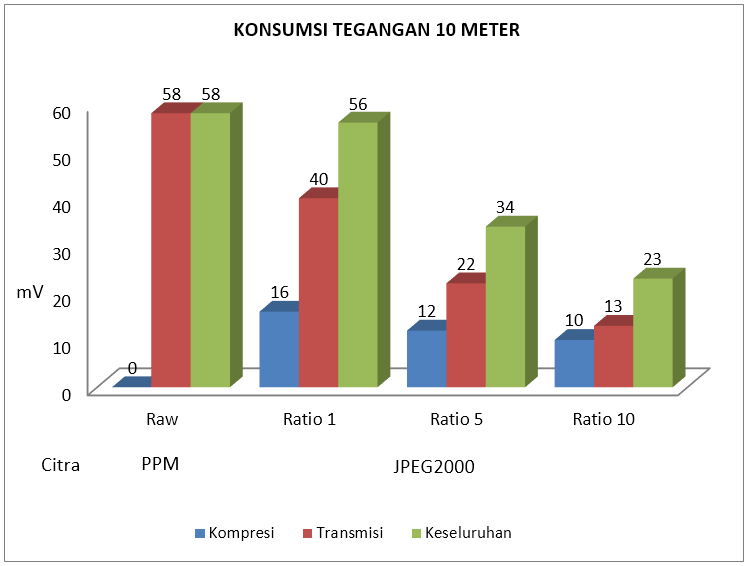 Figure 4.8 shows the power consumption of a transmission line at a distance of 10 meters. The stress consumption decreases constantly with the applied compression ratio. The difference in power consumption is only transmitted uncompressed images with a more efficient compressed 18 mV for a ratio of 1, 1.36 mV and 45 mV for a ratio of 5 and a ratio of 10. If compression consumption is involved, consumption while compression is still more efficient. The difference in power consumption as a whole uncompressed and compressed image, saves 2 mV for a ratio of 1.24 mV and 35 mV for a ratio of 5 and a ratio of 10. 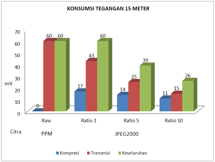 Figure 4.9 shows the power consumption of a transmission line at a distance of 15 meters. The stress consumption decreases constantly with the applied compression ratio. The difference in power consumption is only transmitted uncompressed images with a more efficient compressed 17 mV for a ratio of 1.35 mV and 45 mV for a ratio of 5 and a ratio of 10. If it is involved consumption while compression is still more efficient. The difference in power consumption as a whole uncompressed and compressed image is the same for the ratio 1, 21 mV and 34 mV for the ratio 5 and the ratio 10. 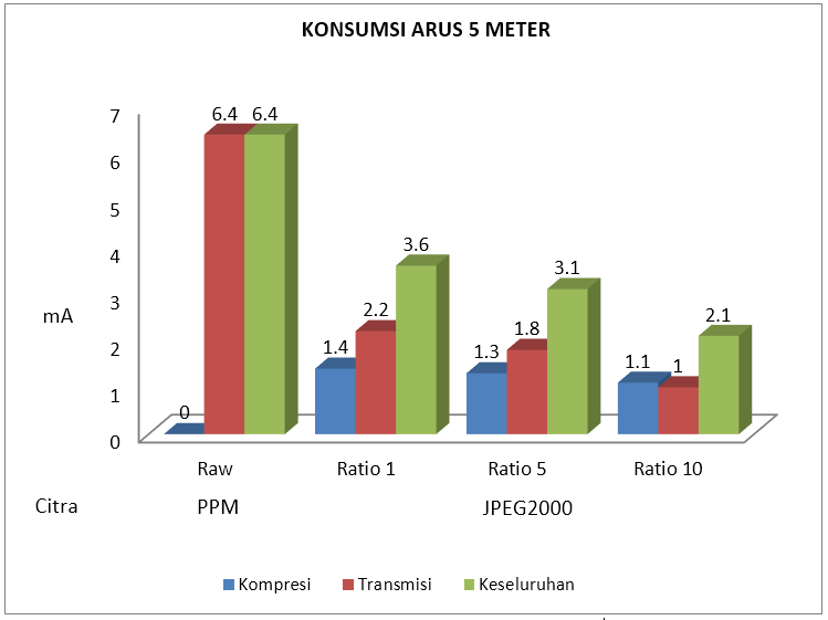 Figure 4.10 shows the current consumption of a transmission power at a distance of 5 meters. The consumption of electric current decreases with the applied compression ratio. The difference in electric current consumption is only transmitted uncompressed images with a more efficient 4.2 mA for a ratio of 1, 4.6 mA and 5.4 mA for a ratio of 5 and a ratio of 10. If it is involved consumption while compression is still more efficient. The difference between the overall consumption of uncompressed and uncompressed images is more efficient 2.8 mA for a ratio of 1, 3.3 mA and 4.3 mA for a ratio of 5 and a ratio of 10. 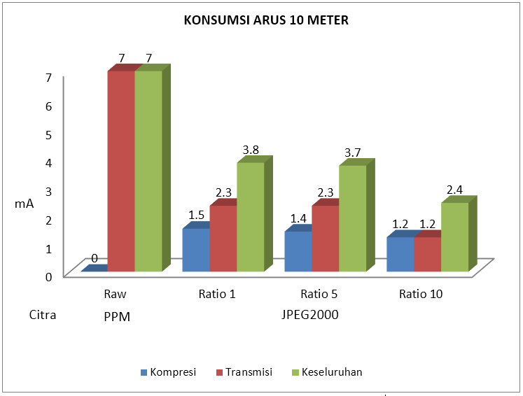 Figure 4.11 shows the current consumption of a transmission power at a distance of 10 meters. The consumption of electric current decreases with the applied compression ratio. The difference in electric current consumption is only transmitted uncompressed images with a more efficient 4.7 mA for a ratio of 1, 4.7 mA and 5.8 mA for a ratio of 5 and a ratio of 10. If it is involved consumption while compression is still more efficient. The difference between the overall consumption of uncompressed and compressed images is more efficient 3.2 mA for a ratio of 1, 3.3 mA and 4.6 mA for a ratio of 5 and a ratio of 10. 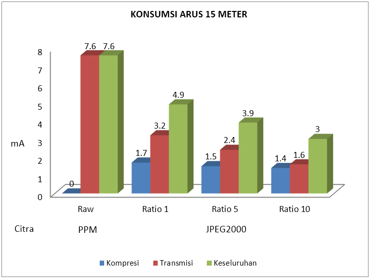 Figure 4.12 shows the current consumption of a transmission power at a distance of 15 meters. The consumption of electric current decreases with the applied compression ratio. The difference in electric current consumption between uncompressed and compressed images with a more efficient 4.4 mA for a ratio of 1, 5.2 mA and 6 mA for a ratio of 5 and a ratio of 10. If it is involved consumption while compression is still more efficient. The difference in electric current consumption as a whole uncompressed and compressed images is more efficient 2.7 mA for a ratio of 1, 3.7 mA and 4.6 mA for a ratio of 5 and a ratio of 10. 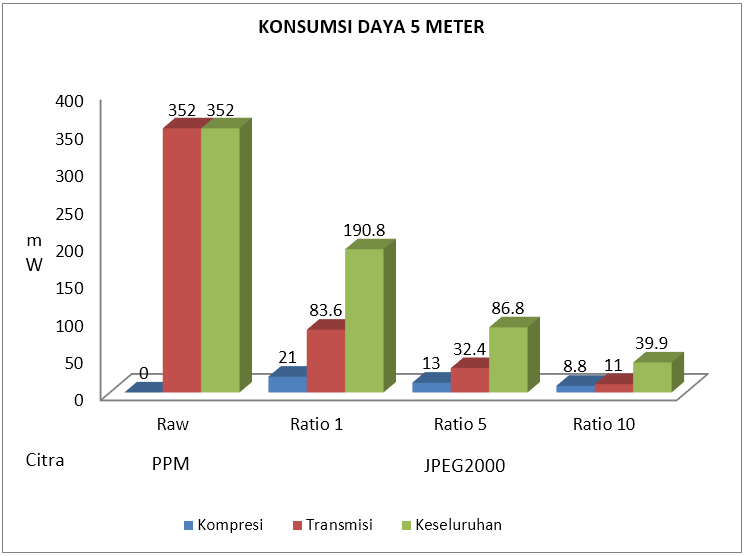 Figure 4.13 shows the power consumption of transmission electricity at a distance of 5 meters. The power consumption decreases drastically with respect to the compression ratio applied. The difference in power consumption between uncompressed and compress images are more efficient 268.4 mW for a ratio of 1, 319.6 mW and 341 mW for a ratio of 5 and a ratio of 10. If it is involved consumption while compression is still more efficient. The difference between the overall consumption of uncompressed and compressed images is 161.2 mW for a ratio of 1,265.2 mW and 312.1 mW for a ratio of 5 and a ratio of 10.meter. 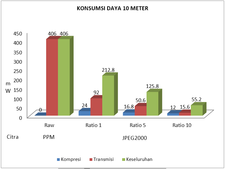 Figure 4.14 shows the power consumption of a transmission at a distance of 10 meters. The power consumption decreases drastically with respect to the compression ratio applied. The difference in power consumption is more efficient compressed 314 mW for a ratio of 1, 355.4 mW and 390.4 mW for a ratio of 5 and a ratio of 10. If it involves consumption while compression is still more efficient. The difference between the overall consumption of uncompressed and compressed images is 193.2 mW for a ratio of 1, 280.2 mW and 350.8 mW for a ratio of 5 and a ratio of 10. 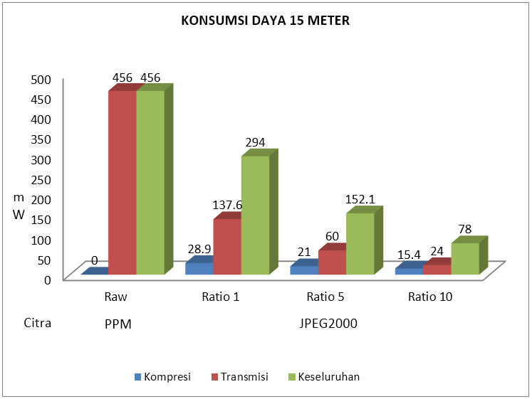 Figure 4.15 shows the power consumption of a transmission at a distance of 15 meters. The power consumption decreases drastically with respect to the compression ratio applied. The difference in power consumption is more efficient compressed 318.4 mW for a ratio of 1, 396 mW and 432 mW for a ratio of 5 and a ratio of 10. If it involves consumption while compression is still more efficient. The difference between the overall consumption of uncompressed and compressed images is 162 mW more efficient for a ratio of 1, 303.9 mW and 378 mW for a ratio of 5 and a ratio of 10. From Figure 4.7 - Figure 4.15 it can be concluded that in terms of power consumption and compression processing time is very low but it can significantly reduce the transmission load so it is highly recommended to use it. By applying a higher compression ratio, it will reduce the current and voltage consumption when the automatic transmission of the electric power consumed is lower. Also as the compression ratio increases, the current consumption and the power supply voltage decreases so that it is ensured that increasing the compression ratio will lighten the transmission load. The farther the transmission distance, the greater the power consumption, but the difference between the distances of 5 meters, 10 meters and 15 meters is not significant. 4.4.2 Transmission Processing TimeApart from the consumption of electric power, from a time perspective there is also a drastic effect of compression, but there is almost no visible effect in terms of distances of 5 meters, 10 meters, and 15 meters. Figure 4.16 shows the time required for compression and transmission, while Figure 4.17 represents the overall time required which is a combination of compression and transmission. 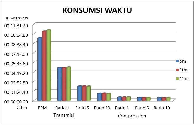 Figure 4.16 shows that compression takes a very short time and very lowers the time required for transmission. The greater the compression ratio that is applied, the smaller the transmission time. The compression time will take 25-30 seconds. The transmission time is getting smaller from raw image to compressed image with ratio of 10 with a value of about 10 minutes 30 seconds, 5 minutes, 2 minutes, and 1 minute. 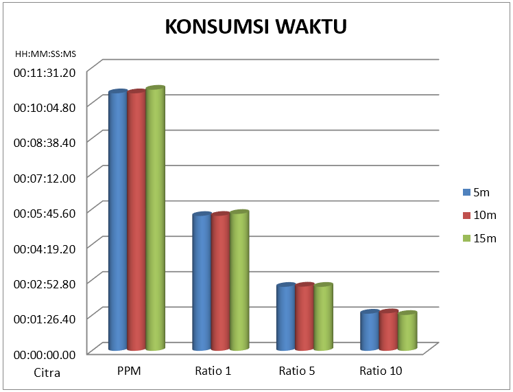 Overall from a distance perspective it doesn't seem to matter but compression, which plays a role in shortening the transmission time. An image that is compressed with a ratio of 10 takes an overall time of 1 minute 30 seconds, a ratio of 5 2 minutes 30 seconds, a ratio of 1 4 minutes 30 seconds, and 10 minutes for an uncompressed image. 4.4.3 Image QualityIn terms of time, it is also seen in terms of image quality using the PSNR size. 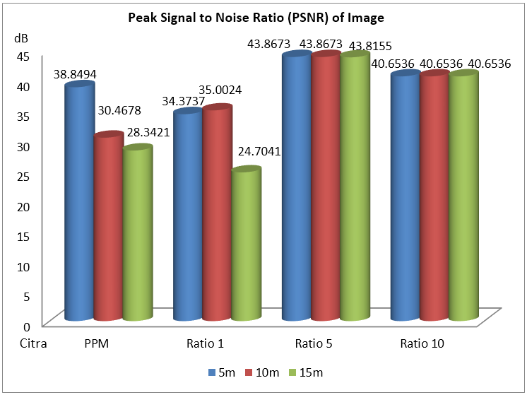 Figure 4.18 shows the uncompressed PSNR image after transmission at a distance of 5 meters, 10 meters, 15 meters. The ratio of 10 both of 5 meters, 10 meters and 15 meters has the same PSNR of 40.6536, similarly to the ratio of 5 around the value of 43.8. The effect of distance is seen in ratio 1 and without compression, for ratio 1 the PSNR value is around 35 for 5 meters and 10 meters, and drops significantly at 15 meters with a PSNR value of 24.7041. The effect of distance can be seen in the image without compression, for ratios 5 and 10, the effect of distance is not visible. In the image without compression, the PSNR value decreases with the farther distance, 5 meters, 10 meters, and 15 meters, respectively, is 38.8494, 30.4678, 38.3421. So it can be concluded that ratio 1 has the worst quality after uncompressed image, while ratio 10 has promising quality, and ratio 5 shows the best quality. From the viewpoint, the image with PSNR below 40 dB looks clearly not like the original. The cause is a transmission error. 4.4.4 File Size and Memory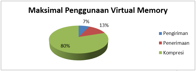 Figure 4.19 shows the maximum virtual memory used, and the most widely used during compression. For compression using a maximum of 14548 kB of virtual memory and sending using 1256 kB at the transmitter, the receiver uses a maximum of 2336 kB of virtual memory for reception. 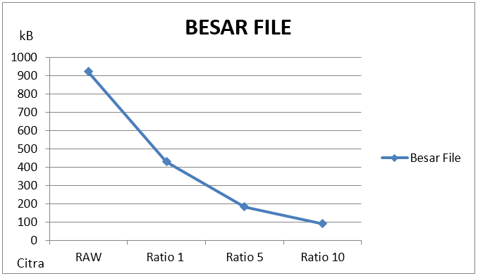 Figure 4.20 shows the uncompressed and uncompressed image file size, the file size decreases by applying a larger ratio. The file size for the uncompressed image is 921.6 kB, the ratio 1 429.9 kB, the ratio 5 184.2 kB, and the ratio 10 91.7 kB. In terms of image quality, the original image and the compressed ratio of 1 have lower PSNR than other images, and it can be seen from the image that there is a transmission error. Then the larger the file size, the more sensitive it is to errors. Chapter 5 Closing5.1 ConclusionFrom this overall research, it can be concluded as follows:
5.2 Future WorkBy successfully transmitting images to Imote2 Linux, this tool can be used for both fieldwork and further research. The following are suggestions for further research:
Image             Bibliography
Catatan
Daftar Isi
AbstrakBeberapa tahun ini jaringan sensor nirkabel (JSN) telah memberikan trobosan dalam bidang monitoring dari monitoring curah hujan di kebun hingga monitoring detak jantung di bidang kesehatan. Teknologi ini dikenal atas konsumsi energi yang sangat rendah dan sederhana, bahkan saat ini sedang dikembangkan agar dapat beroperasi tanpa sumber daya, melainkan menggunakan energi sekitar yang tersedia seperti menggunakan masukkan energi dari gelombang elektromagnetik stasiun TV. JSN awalnya fokus pada data yang dapat dikirim pada kapasitas kanal bit rate rendah. Di penelitian ini lebih kepada JSN dengan kapasitas kanal bit rate yang lebih tinggi agar dapat transmisi data multimedia khusus disini adalah transmisi citra, sehingga istilah JSN dapat diturunkan menjadi jaringan sensor visual nirkabel (JSVN). Platform yang digunakan adalah Imote2 dengan radio berbasis IEEE 802.15.4 ZigBee serta ciri khas utama dari penelitian ini adalah mengimplementasi embedded system Linux, yang belum pernah dilakukan sebelumnya. Selama ini tidak ada publikasi yang mendeskripsikan skema transmisi citra di Imote2 Linux, dengan kata lain belum ada informasi yang berkaitan dengan transmisi citra. Di penelitian ini dibahas secara detil skema transmisi citra antar Imote2 Linux versi penulis serta skema agar dapat difungsikan sebagai testbed, mulai dari aplikasi yang ditulis dalam bahasa C, kompilasi beberapa kebutuhan testbed, hingga implementasi testbed. Selebihnya kinerja dari Imote2 Linux diuji dengan mentransmisikan citra tanpa kompresi dan dengan kompresi standar JPEG2000 dimana kompresi dilakukan di embedded system Imote2 Linux oleh software OpenJPEG. Hasil menunjukkan perbedaan yang signifikan antara transmisi tanpa kompresi dengan transmisi dengan kompresi. BAB 1 Pendahuluan1.1 Latar BelakangJSN (Jaringan sensor nirkabel) atau lebih dikenal dengan WSN (wireless sensor network) merupakan suatu sistem jaringan nirkabel yang menggunakan perangkat sensor untuk mendapatkan informasi. Sensor-sensor ini didistribusikan di suatu wilayah yang saling terhubung secara nirkabel (membentuk jaringan) untuk mengumpulkan informasi yang ada di sekitarnya seperti pada Gambar 1.1. JSN ini telah diterapkan di bidang sipil, medis, dan lain-lain (Shwe dkk, 2013). Terdapat beberapa jenis sensor antara lain sensor suhu, gerak, kadar keasaman, suara, dan kamera. Pada penelitian ini digunakan WVSN (Wireless Visual Sensor Network) atau JSVN (Jaringan Visual Sensor Nirkabel), yaitu JSN yang berbasis sensor kamera. Salah satu contoh penerapan JSN adalah penelitian Garcia-Sanchez (2010) tentang pemantauan hewan liar terhadap infrastruktur transportasi yang berada di alam liar. Hal yang dipantau adalah interaksi hewan seperti frekuensi dan waktu hewan melintasi jalan raya atau underpass, lama hewan berada pada tempat tersebut, dan bagaimana sikap hewan terhadap infrastruktur transportasi tersebut. Dari pemantauan ini dapat dilihat apakah infrastruktur transportasi aman, menarik perhatian hewan, secara keseluruhan bagaimana keadaan infrastruktur transportasi dan keadaan alam disekitarannya. Pemantauan dilakukan dengan memasang sensor kamera dan sensor gerak platform Imote2 di wilayah infrastruktur transportasi seperti gerbang masuk underpass, dalam underpass, tepi jalan raya, diatas pohon, atau jurang seperti Gambar 1.2. Beberapa faktor seperti tidak ada power source (sumber daya), lingkungan yang tidak memungkinkan untuk instalasi perangkat besar seperti jurang, zona berbahaya, dataran yang tidak merata/miring, dan kondisi mahkluk hidup sekitar yang sensitif (cenderung menyerang perangkat atau menghidari perangkat tersebut), ataupun faktor waktu yang membutuhkan pemantauan segera sehingga tidak mungkin untuk menghabiskan waktu untuk instalasi perangkat besar, dan banyak faktor-faktor lainnya, contoh serupa di bidang militer untuk mendeteksi keberadaan musuh harus menggunakan perangkat minimalis dan berukuran kecil agar tidak mudah dideteksi, untuk hal ini JSN merupakan suatu pilihan karena praktis untuk diterapkan. Penelitian JSN saat ini mengarah pada penghematan energi dengan tetap memaksimalkan kinerja dengan kata lain, mendapatkan informasi sebanyak mungkin dengan konsumsi energy seminimal mungkin.Hal ini dikarenakan JSN memiliki sumber daya yang dan kemampuan komputasi yang terbatas. Imote2 sendiri menggunakan 4 batterai AAA sebagai sumber daya, memiliki kemampuan processing 13-416 MHz, program memory 32 MB, RAM (Random Access Memory) 256 kB sebagai tempat penampung sementara pada tahap processing, dan transmission rate maksimum 250 kbps point-to-point. Walaupun spesifikasi Imote2 unggul dibanding dengan platform lainnya seperti terlihat pada Tabel 1.1 tetapi masih jauh dibanding dengan PC (Private Computer) sekarang yang memiliki spesifikasi minimal processor > 1 GHz, RAM > 1 GB, dan kapasitas harddisk > 50 GB. Dari keterbatasan tersebut salah satu upaya penghematan adalah penentuan media transmisi yang tepat. Terdapat banyak jenis standar untuk media transmisi nirkabel seperti WLAN (Wireless Local Area Network), Broadband Wireless, dan WPAN (Wireless Personal Area Network). WLAN distandarkan pada IEEE 802.11 memiliki jakauan yang luas > 1 km dengan max data rate 54 Mbps pada IEEE 802.11g, standar ini lebih cocok untuk komunikasi nirkabel pada komputer. Broadband Wireless memiliki jangkauan yang lebih luas dengan max data rate IEEE 802.16m 100 Mbps lebih dikenal dengan WMAN (Wireless Metropolitan Area Network). Namun dari hasil penelitian sebelumnya yaitu penelitian Wiasta (2012), Natha (2012), dan penulis sendiri Purnama (2013) tidak effisien dalam transmisi data biner menggunakan WLAN. Hasilnya jauh bila dibandingkan dengan menggunakan standar WPAN dapat dilihat pada Gambar 1.3. Untuk perangkat portable disediakan standar IEEE 802.15 WPAN. IEEE 802.15.1 Bluetooth menyediakan maxdata rate 723.2 kbps dengan jangkauan 10 meter biasa digunakan untuk transmisi suara dan data, diaplikasikan pada handphone dan gadget. IEEE 802.15.2 mengatur komunikasi antar WPAN dengan jaringan nirkabel lainnya. IEEE 802.15.3 HR-WPAN (High Data Rate Wireless Personal Area Network) dengan data rate 11-55 Mbps dengan jangkauan > 70 meter biasa digunakan untuk multimedia. Yang cocok untuk digunakan pada JSN adalah standar IEEE 802.15.4 LR-WPAN (Low Data Rate Wireless Personal Area Network) karena bersifat konsumsi daya rendah dan data rate 20, 40, 250 kbps point-to-point dengan jangkauan 10 meter (Ahmad, 2005). IEEE 802.15.4 mengembangkan PHY layer, MAC layer, dan NWK layer, sedangkan Zigbee mengembangkan application layer selengkapnya dapat dilihat di BAB II. Keterbatasan transmisi pada IEEE 802.15.4 Zigbee adalah data rate maksimal 250 Kbps point-to-point dengan PHY layer maksimal besar paket adalah 127 byte dikurangi dengan header 89 byte. Fragmentation dan reassembly tidak dilakukan pada NWK layer oleh karena itu harus dikembangkan aplikasi pada application layer untuk fragmentation dan reassembly serta disesuaikan untuk transmisi citra (Pekhteryev, 2005). Upaya lain adalah menggunakan sistem operasi yang ringan. Sebelumnya Imote2 bekerja pada Intel Platform X. Setelah Imote2 Pindah ke Crossbow, Intel Platform X tidak lagi dikembangkan karena Crossbow mengeluarkan sistem operasinya sendiri. Sistem operasi yang digunakan kebanyakan sistem operasi yang dikembangkan oleh komunitias seperti SOS (Simple Operating System) tetapi SOS berhenti dikembangkan sejak tahun 2008. Sekarang ini yang digunakan adalah TinyOS dan yang terbaru Linux. Kebanyakan publikasi di web menggunakan TinyOS. Sekarang dikembangkan embedded Linux karena ditemukan batasan-batasan pada TinyOS seperti routing yang kompleks. Komunitas embedded Linux memandang sistem operasi Linux pada Imote2 dapat mengatasi keterbatasan tersebut. Namun embedded Linux pada Imote2 masih bersifat baru dan sedang dikembangkan (Kasteleiner, 2010). Alasan utama digunakan Linux karena bersifat opensource yang artinya gratis, terbuka dan boleh dikembangkan oleh siapapun. Penelitian ini mengarah ke emebedded system Imote2 Linux. Sebelum telah berhasil mengembed Linux ke platform Imote2 dan berhasil mengirim data acak maksimal 28 byte, kali ini agar Imote2 Linux dapat mentransmisikan citra dengan radio berbasis IEEE 802.15.4 ZigBee. Setelah dapat melakukan transmisi akan diamati kinerja transmisi Imote2 Linux. 1.2 Rumusan Masalah
1.3 Tujuan Penelitian
1.4 Manfaat Penelitian
1.5 Batasan Masalah
BAB 2 Tinjauan Pustaka2.1 Penelitian SebelumnyaPada penelitian sebelumnya adalah implementasi embedded Linux pada JSVN platform Imote2. Pertama Imote2 menggunakan sistem operasi dari Crossbow. Setelah itu diinstalasi TinyOS, sekarang dicoba digunakan embedded Linux. Ada 3 hal yang dibahas yaitu prosedur instalasi embedded Linux, konfigurasi pasca instalasi, dan diamati kinerja JSVN platform Imote2 dengan mengukur memory yang dikonsumsi dan daya listrik yang dikonsumsi saat mentransmisikan data biner. Prosedur instalasi meliputi cross compile Linux kernel dan driver ke arsitekur ARM yaitu yang digunakan oleh Imote2, penyiapan bootloader dan filesystem, dan pengembedan/pemasukan bootloader, kernel, dan filesystem ke Imote2 menggunakan software OpenOCD chip debugger. Untuk melakukan hal ini diperlukan komputer dengan sistem operasi Linux. Pasca pengembedan/pemasukan diaktifkan jaringan IP (Internet Protocol), SSHD (Secure Shell Daemon), dan radio melalui Telnet. Perintah untuk konfigurasi hal tersebut bersifat umum yang digunakan pada Linux berbasis Debian, Ubuntu, dan sejenisnya. Tahap akhir penelitian adalah mengamati kinerja pentransmisian data biner pada jarak 10m, 20m, dan 30m. Transmisi dicoba pada 2 jenis media transmisi nirkabel yaitu IEEE 802.11 WLAN dan IEEE 802.15.4 Zigbee juga disebut LR-WPAN. Perlu ditambahkan catu daya dan perangkat radio WLAN TP-LINK untuk mengimplementasikan WLAN. Dibuatkan daughter board untuk menghubungkan perangkat, dari segi software dibutuhkan driver.Sedangkan pengimplementasian Zigbee telah tersedia di Imote2, tinggal menjalankan driver dan membuat script untuk mentransmisikan data biner. Pada hasil akhir Zigbee lebih hemat dari segi konsumsi tegangan dan arus listrik dapat dilihat pada Gambar 2.1, Gambar 2.2, dan Gambar 2.3. Nilai konsumsi daya listrik adalah hasil perkalian dari tegangan dan arus listrikpada gambar sebelumnya yaitu gambar 1.2 (Natha, 2012, Wiasta, 2012, Purnama, 2013). 2.2 Tinjauan Mutahir (State of The Art)Penelitian ini adalah lanjutan dari penelitian sebelumnya yang akan meneliti kinerja JSVN platform Imote dengan sistem operasi embedded Linux dalam mentransmisikan citra melalui media transmisi berbasis IEEE 802.15.4 Zigbee. Jika sebelumnya hanya mentransmisikan data biner, kali ini mentransmisikan citra. Diutamakan mengunakan media transmisi berbasis IEEE 802.15.4 Zigbee karena terbukti sebelumnya lebih effisien. Gagasan untuk meneliti pentransmisian citra dengan 4 skalabilitas yang berbeda berdasarkan wavelet (tahap penelitian pada BAB III) didapatkan dari penelitian Nasri (2010). Penelitian Nasri (2010) meneliti penerapan JPEG2000 secara distributif transmisi citra pada JSVN. Secara rinci skema JSVN dibagi atas 7 cluster (7 kelompok perangkat JSVN) dimana masing-masing cluster diberi sebagian tahap standar kompresi JPEG2000 (JPEG200 dapat dilihat pada sub-bab 2.6) dapat dilihat pada Gambar 2.4. Dengan skenario ini muncul gagasan untuk mentransmisikan citra dengan skalabilitas yang berbeda berdasarkan standar JPEG2000 dalam penelitian pada penulisan ini.
Secara ringkas hasil konsumsi energi tertinggi ada pada cluster pertama dan kedua, selanjutnya konsumsi energi bersifat menurun dari cluster kedua hingga ketuju. Hasil didapatkan dengan menggunakan rumus konsumsi energi khusus tahap JPEG2000, dengan kata lain Penelitian Nasri (2010) bersifat simulasi, bukan penelitian yang menggunakan perangkat langsung. Penelitian berkaitan adalah kinerja kompresi dan transmisi menggunakan IJG (Independent JPEG Group) library pada platform Imote2 dengan TinyOS berdasarkan hasil penelitian oleh Mowafi (2010). Skenario berupa koneksi single-hop atau point-point dimana perangkat JSVN melakukan kompresi JPEG terhadap citra terlebih dahulu sebelum melakukan transmisi. Citra dikompresi dengan quality factor lipatan 5 dari 95-5. Diukur waktu dan drop tegangan saat kompresi dan transmisi serta diukur PSNR citra. Hasil pengukuran menunjukan konsumsi waktu dan tegangan terhadap proses kompresi citra relatif sama terhadap nilai quality factor, dengan nilai mendekati 0. Sedangkan hasil pengukuran transmisi menunjukan memerlukan waktu dan tegangan rata-rata 14 detik dan 0.45 mV pada quality factor 95 dan menurun hingga 1 detik dan 0.03 mV pada quality factor 5. Rentang PSNR dari quality factor 95-5 adalah 47-28 dB.Sehingga kompresi citra JPEG membantu untuk menghemat waktu dan energi dalam transmisi citra. Hasil penelitian dapat dilihat dari pada Gambar 2.5. Pada makalah lain Mowafi (2012) mengimplementasikan IJG dan JPEG2000. Dilakukan variasi quality factor pada IJG dan Compression Ratio pada JPEG2000 dengan menemukan besar file yang sama pada kedua teknik kompresi tersebut. Setelah itu dilakukan perbanding terhadap kedua teknik kompresi tersebut dengan mengukur waktu untuk kompresi, waktu transmisi setelah kompressi, dan konsumsi energi terhadap bit rate. Pengukuran PSNR dari kedua teknik kompresi tersebut juga dilakukan berdsarkan besar file. Terakhir dilakukan simulasi dengan multi-hop sensor dimana waktu dan komsumsi energi menjadi tolak ukur terhadap kedua teknik kompresi tersebut.Parameter didapatkan dari penelitian single-hop sebelumnya. Hasilnya JPEG2000 unggul di sisi PSNR, konsumsi daya listrik saat transmisi, dan waktu transmsisi tetapi JPEG unggul di sisi konsumsi daya listrik dan waktu saat kompresi. Konsumsi saat kompresi pada JPEG paling sedikit dibanding dengan askpek lain, sedangkan konsumsi saat kompresi pada JPEG2000 sebaliknya yaitu paling besar, dari proses keseluruhan kompresi dan transmisi. Hasil penelitian dapat dilihat pada Gambar 2.6. Sehingga disimpulkan JPEG lebih efisien pada JSVN dengan hop (lompatan) yang pendek karena hemat di sisi kompresi, tidak membutuhkan jalur transmisi yang panjang. Jika dengan hop yang panjang disarankan menggunakan JPEG2000 karena lebih hemat di sisi transmisi. JSVNakan lebih optimal bila diterapkan teknik kompresi yang bervariasi agar bersifat fleksibel terhadap keadaan. Penelitian Pekhteryev (2005) adalah mentransmisikan citra pada jaringan IEEE 802.15.4 dan Zigbee sangat mirip dengan penelitian ini. Disebabkan oleh kapasitas transmisi yang sangat terbatas dan tidak disediakan fitur fragmentation dan reassembly pada NWK layer diharuskan membuat suatu aplikasi dengan fitur tersebut. Penelitiannya adalah mengamati jumlah pengiriman citra yang error dari pengiriman 100 citra JPEG dan 100 citra JPEG2000 pada jaringan 1-hop dan 2-hop seperti Gambar 2.7, hasil dapat dilihat pada Gambar 2.8 dan 2.9. Penelitian ini mengimplementasikan transmisi citra pada transmisi IEEE 802.15.4 Zigbee seperti penelitian Pekhteryev (2005). Perbedaan dari penelitian ini adalah penelitian Pekhteryev (2005) menggunakan perangkat M16C mikrokontroller dan lebih menganalisis error transmisi sedangkan penelitian ini menggunakna perangkat platform Imote2 dan lebih menganalisis effisiensi energi transmisi. Selanjutnya akan dicoba bila citra dikompresi terlebih dahulu menggunakan standar JPEG2000 sebelum ditransmisikan seperti penelitian Mowafi (2012). Perbedaan dari penelitian ini dengan Mowafi (2010, 2012) adalah sistem operasi yang digunakan, penelitian Mowafi (2010, 2012) menggunakan TinyOS sedangkan penelitian ini menggunakan embedded Linux. Selain itu tidak ada penelitian (dari pengetahuan penulis) yang membahas skema transmisi citra pada JSVN IEEE 802.15.4 Zigbee khususnya di embedded system Imote2 Linux. Inti dan perbedaan mendasar dari penelitian ini terhadap yang lain adalah dibuat program transmisi citra dalam bahasa C dan skema agar dapat berfungsi sebagai testbed di Imote2 Linux. 2.3 Daya ListrikDaya listrik merupakan tenaga listrik, secara matematis didefinisikan sebagai energi listrik yang dihasilkan per waktu. P=dw/dt (2.1) Dimana: p = daya listrik (watt) w = energi listrik (joule) t = waktu (detik) Daya listrik dapat dibentuk dari perkalian tegangan listrik dan arus listrik. Jika tegangan listrik adalah energi listrik rata-rata per muatan listrik, dan arus listrik merupakan muatan listrik yang mengalir tiap detik maka perkalian kedua variabel tersebut menghasilkan daya listrik (Irwin, 1993). V=dw/dq, I=dq/dt, VI=(dw/dq)(dq/dt)=(dw/dt)=P (2.2) Dimana: V = tegangan listrik (volt) q = muatan listrik (coloumb) I = arus listrik (ampere) 2.4 Standar IEEE 802.15.4 ZigbeeStandar ini merupakan kerjasama antar IEEE (Institute of Electronic and Electrical Engineer) dan ZigBee. IEEE fokus mengembangkan standar pada layer dibawahnya yaitu PHY (Physical) layer dan MAC (Media Access Control) atau datalinklayer. Sedangkan ZigBee fokus mengembangkan layer diatasnya, sampai application layer. Standar IEEE 802.15 khusus pada WPAN (Wireless Personal Area Network) dengan tujuan konsumsi daya listrik rendah, jarak pendek, dan ukuran alat kecil. Jika 802.15.1 (bluetooth) merupakan standar menengah, 802.15.3 merupakan HR(high rate)-WPAN dengan data rate tinggi, maka 802.15.4 merupakan LR(low rate)-WPAN dengan data rate rendah namun konsumsi daya listrik rendah. Sedangkan 802.15.2 merupakan standar untuk menghubungkan antar jenis perangkat wireless (Ergen, 2004). 2.4.1 PHY LayerMerupakan layer paling bawah yang mengatur transmisi. Pembentukan symbol menggunakan modulasi O-QPSK (Offset Quadriture Phase Shift Keying) untuk mengurangi konsumsi pada transmisi. Operating frequency bands dibagi atas 27 channel berdasarkan DSSS (Direct Sequence Spread Spectrum) seperti pada gambar 2.11. Channel 0 berada pada frekuensi 868.3 MHz dengan data rate 20 Kbps, channel 1-10 berada pada frekuensi 902 Mhz dengan jarak antar channel 2 MHz dengan data rate 40 Kbps, dan channel 11-26 berada pada frekuensi 2.4 GHz dengan jarak antar channel 5 MHz dengan data rate 250 Kbps. Sensitivitas minimum channel 0-10 -92dBm sedangkan channel 11-26 adalah 85 dBm (Ergen, 2004), selengkapnya dapat dilihat pada tabel 2.1. Fitur dari PHY layer (Ergen, 2004):
2.4.2 MAC LayerMAC layer merupaka layer yang mengatur aliran data dari PHY layer menuju network layer dan sebaliknya. Suatu perangkat dapat berupa FFD (Full Function Device) atau RFD (Reduced Function Device). Suatu FFD dapat berfungsi sebagai PAN (Personal Area Network) coordinator, coordinator, atau member. MAC layer mengatur perangkat sebagai berikut (Ergen, 2004):
2.4.3 Network LayerNetwork layer mengatur jaringan termasuk mekanisme routing. Pada layer ini secara umum menggunakan dua algoritma yaitu AODV (Ad Hoc On Demand Distance Vector) dan Cluster-Tree algorithm milik Motorola (Ergen, 2004).
2.4.4 Application LayerLayer ini terdiri dari application framework dan application support (APS) sublayer. Application framework mengatur komunikasi yang menghubungkan antara end-user dengan layer dibawah application. Sedangkan application support sublayer mengatur hubungan antara application framework dan network layer, secara spesifik mengatur application profile, cluster, dan endpoints. Application profile menggambarkan sekumpulan perangkat yang berkerja pada suatu aplikasi spesifik, contohnya application profile untuk home automation system dan commercial, industry dan institutional. Suatu perangkat pada sebuah application profile berkomunikasi dalam sebuah cluster, contohnya pada home automation profile terdapat cluster yang mengatur subsistem pencahayaan. Sedangkan endpoints merupakan entitas komunikasi, yang telah ditentukan mengenai aplikasi yang dijalankan contohnya tombol pada remote control. Hal yang penting dari application support sublayer adalah binding, dimana disini diartikan sebagai penghubung antar endpoints contohnya untuk menghidupkan lampu dengan tombol pada remote. Binding dapat bersifat direct maupun indirect. Hubungan langsung antara remote dengan lampu merupakan direct binding. Yang bersifat indirect binding terdapat penerus diantara remote dengan lampu, biasanya terdapat cluster library. Perintah pada cluster library ada yang dapat dipakai bersama, hanya perlu ditambahkan cluster ID pada perintah tersebut, contohnya perintah on/off yang perlu ditambahkan cluster ID terhadap perangkat yang dituju (Daintree Network, 2006). Fragmentation dan reassembly tidak dilakukan pada NWK layer oleh karena itu harus dikembangkan aplikasi pada application layer untuk fragmentation dan reassembly serta disesuaikan untuk transmisi citra (Pekhteryev, 2005). 2.5 Intel Mote 2 (Imote2)Imote2 merupakan platform pada perangkat JSN yang dikembangkan oleh Intel Research pada bagian penelitian Platform X. Perangkat ini dibangun dengan konsumsi daya listrik yang rendah, dengan processor PXA271 XScale CPU, dan terintegrasi pada IEEE 802.15.4 ZigBee (Stanford, 2013). Processor ini (Intel Xscale processor PXA271) dapat beroperasi pada tegangan rendah (0.85V) dan frekuensi 13MHz hingga 104MHz. Frekuensi dapat dinaikkan hingga 416MHz dengan mengatur tegangan. Secara umum Imote2 terdiri dari 4 bagian seperti terlihat pada Gambar 2.21. 2.5.1 Radio Processor Board IPR2400Spesifikasi IPR2400 dapat dilihat sebagai berikut (crossbow, 2007):
2.5.2 Interface Board IIB400Spesifikasi IIB400 dapat dilihat sebagai berikut (crossbow, 2007):
2.5.3 Sensor Board IMB400Spesifikasi IMB400 dapat dilihat sebagai berikut (crossbow, 2007):
2.5.4 Power Supply Board IBB2400Spesifikasi IBB2400 dapat dilihat sebagai berikut (crossbow, 2007):
2.6 JPEG2000JPEG2000 merupakan standar kompresi citra yang dikembangkan oleh JPEG (Joint Photographic Expert Group) sekitar tahun 2000 dengan harapan standar kompresi citra ini yang berdasarkan DWT (Discrete Wavelet Transform) memberikan kualitas yang lebih baik dari pada standar kompresi citra sebelum yang dikembangkan pada tahun 1992 yaitu JPEG yang berdasarkan DCT (Discrete Cosine Transform). Adapun keunggulan JPEG2000 dengan JPEG sebagai berikut:
Secara umum teknis dari kompresi citra JPEG2000 dapat dilihat pada gambar 2.22 dan sebaliknya bersifat terbalik. Standar kompresi citra JPEG2000 diatur pada ISO/IEC 15444 yang terdiri dari 14 bagian, karakteristik dasar dari JPEG2000 diatur pada bagian pertama yaitu ISO/IEC 15444-1 core coding system. Pengkodean pada JPEG2000 dapat dilihat pada gambar 2.23. 2.6.1 Codestream syntaxSebelum citra dapat dilakukan DWT, maka citra tersebut harus dikonversi menjadi sinyal. Hal tersebut dilakukan pada bagian codestream syntax. Pada bagian ini terdapat header baik header inti atau header tile. Header terdiri dari beberapa marker segment yang mengandung informasi minimalis mengenai suatu komponen, contohnya besar tile, ROI (Region of Interest), dan kuantisasi, dapat dilihat pada Tabel 2.2 dan Tabel 2.3 (Boliek, 2000). 2.6.2 Data OrderingPada bagian ini dilakukan pembagian suatu citra menjadi beberapa komponen. Pada bagian inilah dilakukan tiling seperti gambar 2.24 yaitu pembagian citra menjadi kotak-kotak, sehingga pengkodean tidak harus dilakukan pada seluruh citra, pengkodean dapat dilakukan pada bagian tertentu, contohnya peningkatan resolusi dapat dilakukan pada bagian tertentu tidak harus seluruh citra. Setelah itu tile-tile tersebut dibagi atas beberapa resolusi dan sub-band antara lain terdapat sub-band LL, LH, HL, dan HH seperti pada Gambar 2.25. Resolusi dibagi menjadi precincts, dan sub-band dibagi menjadi code-blocks. Data tersebut didistribusi pada 1 atau lebih layer dimana informasi kandungan masing-masing layer disimpan dalam paket. Terakhir adalah progression order yang memungkinkan multiresolusi, tingkat resolusi akan meningkat seiring dengan pengiriman data, dengan kata lain tidak perlu mengambil semua data untuk menampilkan citra (Boliek, 2000). 2.6.3 Arithmetic Entropy CodingSetelah mendapatkan koefisien tahap selanjutnya adalah arithmetic entropy coding dimana suatu informasi direpresentasikan dalam bentuk digital. JPEG2000 menggunakan Elias entropy coding dimana suatu integer positif x direpresentasikan sebagai 1 + floor(log(2)x). Karena citra telah dibagi atas beberapa tile maka coding dilakukan pada masing-masing tile (Boliek, 2000). 2.6.4 Coefficient Bit ModelingPada bagian ini informasi yang penting atau langka muncul disaring. Masing-masing koefisien pada sub-band telah dibagi menjadi code blocks seperti gambar 2.26. Setelah itu code block siap untuk memasuki coding passes. Coding passes terdiri dari 3 yaitu (Boliek, 2000):
2.6.5 QuantizationKuantisasi merupakan proses pembulatan koefisien. Pada JPEG2000 digunakan rumus 2.3 untuk mencari stepsize kemudian menggunakan rumus 2.4 kuantisasi (Boliek, 2000). ∆b=2Rb−εb(1+(μb/2)) (2.3) ∆b : stepsize Rb : dinamic range sub-band b εb : eksponen μb : mantisa q(u,v)=sign(ab(u,v))(ab(u,v)/∆b) 2.4 2.6.6 TransformPada standar JPEG2000 FDWT (Foward Discrete Wavelet Transform) dilakukan pada masing-masing tile. FDWT melewati koefisien tile dengan low pass filter dan high pass filter untuk mendapatkan koefisien low pass dan koefisien high pass. Level pertama FDWT menghasilkan sub-band LL (Low-Low) yang terdiri koefisien low pass vertical dan low pass horizontal, LH (Low-High) yang terdiri koefisien low pass vertical dan high pass horizontal, HL (High-Low) yang terdiri koefisien high pass vertical dan low pass horizontal, dan HH (High-High) yang terdiri koefisien high pass vertical dan high pass horizontal. Level seterusnya dilakukan FDWT pada sub-band LL, dan sub-band LL baru yang dihasilkan tergantung level yang ditentukan seperti gambar 2.27. Koefisien low pass vertical didapatkan dengan mengaplikasikan low pass filter terhadap tile secara vertikal sedangkan koefisien low pass horizontal didapatkan dengan mengaplikasikan low pass filter terhadap tile secara horizontal dan seterusnya. Pada sisi decoder dilakukan proses IDWT (Inverse Discrete Wavelet Transform) yaitu proses kebalikan dari FDWT (Boliek, 2000). 2.6.7 DC Level, Component TransformForward DC level shift dilakukan sebelum melakukan FDWT. Setelah melakukan forward DC level dapat dilakukan forward component transform untuk mengefisienkan kompresi, namun proses ini boleh tidak dilakukan seperti gambar 2.28 (Boliek, 2000). 2.6.8 Region of InterestROI (Region of Interest) merupakan bagian citra yang akan dikodekan pada codestream terlebih dahulu dengan tujuan bagian ini diberikan kualitas yang lebih besar. Metode yang digunakan adalah Maxshift. Secara umum terdiri dari 4 langkah (Boliek, 2000).
2.7 Peak Signal to Noise RatioPSNR (Peak Signal to Noise Ratio) merupakan suatu ukuran umum digunakan untuk mengukur kualitas citra yang telah diolah terhadap aslinya. Pertama dilakukan perhitungan kesalahan terhadap citra yang telah diolah f(x,y) terhadap citra asli g(x,y). Setelah didapatkan nilai MSE (Mean Square Error) yang akan digunakan untuk mencari nilai PSNR (Shi, 2007). e(x,y)=f(x,y)− g(x,y) (2.5) e : error f : citra terolah g : citra asli x : koordinat horisontal y : koordinat vertikal MSE=(1/MN)ΣM-1x=0ΣN-1y=0e(x,y)2 (2.6) MSE : Mean Square Error M : dimensi horisontal citra N : dimensi vertikal citra PSNRdB=10log10(2552/MSE)dB (2.7) PSNR : Peak Signal to Noise Ratio dalam decibel BAB 3 Metode Penelitian3.1 Lokasi dan Waktu PenelitianPengamatan dan pengambilan data dilakukan di Laboratorium Sistem Komunikasi, Jurusan Teknik Elektro, Fakultas, Universitas Udayana, Jimbaran dan di ruang konferensi, GDLN, Kampus Sudirman, Universitas Udayana. Rencana jadwal penelitian dimulai dari akhir bulan Mei 2014 dan harus selesai sebelum akhir Nopember 2014 lebih detail terdapat di bagian Lampiran. 3.2 Sumber dan Jenis Data PenelitianSumber data dapat dikelompokkan 2 jenis:
Jenis data juga dikelompokkan menjadi 2 jenis:
3.3 Instrumen dan Bahan PenelitianInstrumen penelitian dapat dilihat pada Tabel 3.1 – Tabel 3.5. Perangkat JSVN Imote2 dapat dilihat pada Gambar 2.10.
Bahan penelitian merupakan citra yang ditangkap dari sensor kamera perangkat JSVN Imote2 pada tanggal 9 Mei 2014 di Laboratorium Sistem Komunikasi, Jurusan Teknik Elektro, Universitas Udayana dengan format Portable Pixelmap Graphic (.ppm), resolusi 480 x 640 pixel pada Gambar 3.1, dengan besar file 921.6 KB, dan media transmisi berbasis IEEE 802.15.4 Zigbee. 3.4 Tahapan PenelitianSecara keseluruhan tahap penelitian terdiri dari 2 tahap. Tahap pertama adalah tahap prosedur pengimplementasian transmisi citra menggunakan media transmisi IEEE 802.15.4 Zigbee pada JSVN platform Imote2 dengan sistem operasi embedded Linux. Dijelaskan mekanisme agar dapat mentransmisikan citra. Tahap kedua adalah testbed menguji kinerja JSVN dalam transmisi citra. Kinerja ditentukan oleh konsumsi daya listrik, waktu yang dibutuhkan untuk transmisi, dan besar memory yang digunakan. Secara umum gambaran tahapan dapat dilihat pada Gambar 3.2. 3.4.1 Implementasi IEEE 802.15.4 Zigbee untuk transmisi citraRadio di Imote2 dengan OS Linux dijalankan menggunakan driver Tosmac. Disediakan script oleh Tosmac untuk transmit dan receive yang akan disesuaikan untuk transmisi citra, dapat dilihat sebagai berikut:
//************************************************************
//
// blocking.c
//
// Gefan Zhang
//
//*************************************************************
#include
#include
#include
#include
#include "tosmac.h"

void msg_init(TOS_Msg* pMsg)
{
   pMsg->length = 0;
   pMsg->fcfhi = 0;
   pMsg->fcflo = 0;
   pMsg->dsn = 0;
   pMsg->destpan = 0;
   pMsg->addr = 0;
   pMsg->type = 0;
   pMsg->group = 0;
   memset(pMsg->data, 0, TOSH_DATA_LENGTH);
   pMsg->strength = 0;
   pMsg->lqi = 0;
   pMsg->crc = 0;
   pMsg->ack = 0;
   pMsg->time = 0;
}

//--------------------- main -------------------------------

int main(int argc, char* argv[])
{
  int tosmac_dev;
  TOS_Msg recv_pkt;
  TOS_Msg send_pkt;
  // open as blocking mode
  tosmac_dev = open(TOSMAC_DEVICE, O_RDWR);
  if (tosmac_dev < 0)
  {
    fprintf(stderr, "Open error: %s\n", TOSMAC_DEVICE);
    return 1;
  }
  msg_init(&send_pkt);
  send_pkt.addr = 99;
//  memcpy(send_pkt.data, "DATA for test", 14);
  memcpy(send_pkt.data, "0000000000000", 14);
  send_pkt.length = 14;
  printf("User write to driver\n");
  write(tosmac_dev, (TOS_Msg*)&send_pkt, sizeof(TOS_Msg));
  // close device
  close (tosmac_dev);
  return 0;
}
//************************************************************
//
// blocking.c
//
// Gefan Zhang
//
//*************************************************************
#include
#include
#include
#include
#include "tosmac.h"
void msg_init(TOS_Msg* pMsg)
{
   pMsg->length = 0;
   pMsg->fcfhi = 0;
   pMsg->fcflo = 0;
   pMsg->dsn = 0;
   pMsg->destpan = 0;
   pMsg->addr = 0;
   pMsg->type = 0;
   pMsg->group = 0;
   memset(pMsg->data, 0, TOSH_DATA_LENGTH);
   pMsg->strength = 0;
   pMsg->crc = 0;
   pMsg->lqi = 0;
   pMsg->ack = 0;
   pMsg->time = 0;
}
//--------------------- main -------------------------------

int main(int argc, char* argv[])
{
  int tosmac_dev;
  TOS_Msg recv_pkt;
  TOS_Msg send_pkt;
  // open as blocking mode
  tosmac_dev = open(TOSMAC_DEVICE, O_RDWR);
  if (tosmac_dev < 0)
  {
    fprintf(stderr, "Open error: %s\n", TOSMAC_DEVICE);
    return 1;
  }
  printf("User read from driver:\n");
  read(tosmac_dev, &recv_pkt, sizeof(TOS_Msg));// != sizeof(TOS_Msg);
  printf("length is %d\n", recv_pkt.length);
  printf("data is %s\n", recv_pkt.data);
  // close device
  close (tosmac_dev);
  return 0;
}
3.4.2 TestbedTestbed menggunakan 2 perangkat JSVN Imote2 dimana satu berfungsi sebagai transmitter dan satunya lagi berfungsi sebagai receiver. Pada transmitter dilakukan penangkapan citra dengan sensor kamera. Pada transmitter dilakukan transmisi citra ke receiver melalui media nirkabel berbasis IEEE 802.15.4 Zigbee. Penangkap citra telah dilakukan di penelitian sebelumnya, oleh karena itu hanya diamati pada kompresi dan transmisi. Citra yang ditransmisi terdapat 2 jenis yaitu citra raw dari hasil penangkapan sensor IMB400 dan citra raw yang diolah berdasarkan standar JPEG2000 dengan rasio 1, 5, dan 10 dimana rasio adalah pembatas kapasitas saluran. Rasio 5 berarti jumlah bit dari citra terkompresi dibatasi maksimal 1/5 dari jumlah bit aslinya, dan rasio 10 bearti dibatasi maksimal 1/10 dari jumlah bit aslinya. Pada saat transmisi dilakukan pengukuran konsumsi daya listrik, memory, dan waktu pada transmitter. Pengukuran konsumsi daya listrik menggunakan multimeter dengan obyek pengukuran adalah baterai pada power supply board (IBB2400). Pengukuran daya listrik dilakukan dengan mengukur drop tegangan dan drop arus, dengan kata lain adalah selisih nilai daya listrik sebelum penelitian dan sesudah penelitian. Secara khusus mengukur konsumsi daya listrik dimulai dari pemberian perintah untuk transmisi oleh komputer hingga citra selesai ditransmisikan, demikian pula konsumsi waktu. Pengukuran konsumsi dimulai dari pemberian perintah oleh komputer bukan dari dimulainya transmisi citra karena juga melibatkan aspek sistem operasi yang digunakan yaitu embedded Linux. Data hasil pengukuran adalah dari satu kali penelitian. Memory berdasarkan tampilan dari Terminal saat akses transmitter. Citra yang telah ditransmisi dilakukan pengukuran PSNR. Secara umum testbed dapat dilihat pada Gambar 3.3, Skenario akan dijelaskan pada bagian berikut:
3.5 Alur AnalisisPada bagian ini akan digambarkan tahap penelitian secara diagram alur / flowchart pada Gambar 3.10, Gambar 3.11, dan Gambar 3.12. Penelitian keseluruhan sebagai berikut:
BAB 4 PembahasanSecara keseluruhan pada BAB ini dibahas program transmisi citra, Imote2 Linux sebagai testbed dari kompilasi program transmisi dan software kompresi JPEG2000 hingga pemberian perintah secara nirkabel ke Imote2 yang bertugas sebagai pengirim, dan bagian akhir pada BAB ini ditampilkan dan dianalisa kinerja dari perangkat Imote2. Dari hasil penelitian ternyata melakukan kompresi sebelum transmisi sangat membantu untuk meringankan beban transmisi, dan menariknya proses kompresi itu sendiri tidak terlalu membebankan perangkat, sehingga sangat dianjurkan untuk menggunakan kompresi. Inti dari penelitian ini adalah agar Imote2 Linux dapat difungsikan sebagai testbed. Jika diringkas kembali, penelitian sebelumnya telah berhasil mengembed Linux ke JSVN platform Imote2 dan mentransmisi data acak, maka di penelitian ini adalah untuk mentransmisikan data citra. Kode program pada subbab 3.4.1 adalah program untuk mengirim data karakter maksimal 28 byte, kemudian ditampilkan di layar. Untuk mengirim citra yang dalam bentuk file, kode tersebut harus dimodifikasi agar di sisi pengirim dapat membaca dan mengirim file, dan di sisi penerima dapat menerima dan menyimpan file tersebut (tidak sebatas ditampilkan di layar), juga harus dapat mentransmisikan file lebih dari 28 byte. Proses agar Imote2 Linux dapat berfungsi sebagai testbed dapat diringkas pada Gambar 4.1. Pertama membuat kode program, lebih lengkap dibahas di subbab 4.1. Kemudian program dikompilasi di subbab 4.2 dan subbab 4.3, dan diembed ke Imote2, illustrasi dapat dilihat pada Gambar 4.2. Terakhir Imote2 dikonfigurasi agar dapat menerima perintah via radio, dengan kata lain setelah transmitter dihidupkan, siap untuk menerima perintah, dapat diilustrasikan pada Gambar 4.3. Perintah dapat berupa mengkompresi, maupun mentransmisi citra seperti illustrasi pada Gambar 4.4. Hal ini dilakukan karena transmitter ditenagai dengan baterai (tanpa kabel), sehingga komunikasi hanya tersedia lewat radio. 4.1 Program TransmisiTransmisi menggunakan radio pada Imote2. Di penelitian sebelumnya dijelaskan pada subbab 2.1, menggunakan driver dari Tosmac untuk menjalan radio di Imote2 Linux, disini tetap menggunakan driver yang sama. Untuk transmisi diperlukan 2 program yaitu program untuk mengirim dan menerima. Kedua program tersebut ditulis dalam bahasa C. Khusus pada penelitian ini mengikuti ketentuan dari header tosmac yaitu payload data yang dikirim maksimal 28 byte. Secara keseluruhan di sisi pengirim membaca file citra yang akan dikirim, di penerima akan membuat file baru dan menulis data yang diterima ke file tersebut. Pengiriman dilakukan secara bertahap dengan memecah tile masing-masing berukuran 28 byte (tidak sekaligus). 4.2 Program PengirimSintaks berikut ini menunjukkan program pengirim dengan nama file “send_file_advance.c†yang dilakukan pada penelitian ini dan dijelaskan sebagai berikut: 1 //************************************************************ 2 // 3 // blocking.c 4 // 5 // Gefan Zhang 6 // 7 //************************************************************* 8 // Modified by : Fajar Purnama Baris 1 – 8 merupakan komentar berisi informasi pembuat program dan penulis yang memodifikasi. Komentar dapat ditandai dengan “//†atau dimulai â€/*†dan diakhiri dengan “*/†(yang tidak bold). Baris 5 merupakan penulis pertama dari program, sedangkan baris 8 merupakan nama penulis yang memodifikasi program. 9 #include 10 #include 11 #include 12 #include 13 #include Baris 9 – 13 menunjukkan header yang digunakan pada program ini, header berisi definisi kode yang digunakan. Untuk menggunakan header dapat menggunakan karakter “#â€, karakter ini menunjukkan script yang dibutuhkan oleh program. Di baris 9 terdapat “stdio.h†merupakan header dasar untuk semua program bahasa C yang mendefinisikan perintah “printf†untuk menampilkan ke layar, “while†untuk looping, serta operasi arithmetic, dan masih banyak lainnya. Baris 10 “Fcntl.h†mendefinisikan perintah “open†untuk membuka file serta “close†untuk menutup dan “create†untuk membuat, baris 11 “unistd.h†mendefinisikan perintah “read†untuk membaca file dan “write†untuk menulis data ke file, dan baris 13 “tosmac.h†mengatur variable pada driver tosmac (radio).
14 void msg_init(TOS_Msg* pMsg)
15 {
16 pMsg->length = 0;
17 pMsg->fcfhi = 0;
18 pMsg->fcflo = 0;
19 pMsg->dsn = 0;
20 pMsg->destpan = 0;
21 pMsg->addr = 0;
22 pMsg->type = 0;
23 pMsg->group = 0;
24 memset(pMsg->data, 0, TOSH_DATA_LENGTH); // 28 bytes usually
25 pMsg->strength = 0;
26 pMsg->lqi = 0;
27 pMsg->crc = 0;
28 pMsg->ack = 0;
29 pMsg->time = 0;
30 }
Baris 14 – 30 ditulis dalam bentuk fungsi “msg_init†merupakan fungsi untuk menginisialisasikan variable pada paket seperti address, group, dan payload yang terdapat pada header “tosmac.h†untuk ditransmisikan. Inti program “int main†dimulai dari baris 32.
31 //---Main-Program---//
32 int main(int argc, const char *argv[]){
33 // Check Error
34 if(argv[1]==NULL){
35 printf("Usage: ./send_file [file], example: ./send_file_advance image.ppm");
36 return 1;
37 }
38 //sleep(10); //pause for 10 sec (give time for receiver to prepare) cross this out if not needed
39 // Declaration
40 int tosmac_dev, file, file_size, h, i, j, k;
41 //char *packet;
42 TOS_Msg recv_pkt;
43 TOS_Msg send_pkt;
44 // open as blocking mode
45 tosmac_dev = open(TOSMAC_DEVICE, O_RDWR);
46 if (tosmac_dev < 0)
47 {
48 fprintf(stderr, "Open error: %s\n", TOSMAC_DEVICE);
49
50 return 1;
51 }
52 // open file to be send
53 file = open(argv[1], O_RDWR); // open file
54 file_size = lseek(file,0,SEEK_END); // calculate filesize by going to final byte of file using lseek function from fcntl.h
55 lseek(file,0,SEEK_SET); // return to start of file
56 msg_init(&send_pkt);
57 send_pkt.addr = 99;  // Address
58 h = file_size/TOSH_DATA_LENGTH; // How much packet or times of transmission should be prepared (using div)
59 i = file_size%TOSH_DATA_LENGTH; // Remainder of "h" (using mod)
60 j = 0;
61 k = 0;
Baris 33 – 37 terdapat pemeriksaan error bila perintah yang dimasukkan tidak sesuai, Baris 39 – 43 adalah bagian deklarasi variable, Baris 44 – 51 membuka radio, baris 52 – 55 membuka file, dan baris 56 – 61 menentukan paket. Pada baris 32 “int main†terdapat “int argc, int argv[]†agar program dapat dieksekusi dengan memilih file yang diinginkan “./send_file_advance argv[1]â€, seperti yang didefinisikan pada baris 53 “file = open(argv[1], O_RDWR)â€. Jika tidak terdapat input maka akan menampilkan cara penggunaan program di baris 35 yaitu “./send_file_advance file†yang diatur pada pernyataan “if(argv[1]==NULL)†baris 34, dan baris 36 “return 1†untuk memberik kode error pada program jika input sesuai dengan pernyataan baris 34. Baris 45 “tosmac_dev = open(TOSMAC_DEVICE, O_RDWR)†adalah untuk membuka radio dimana “TOSMAC_DEVICE†merupakan “/dev/tosmac†seperti didefinisikan pada “tosmac.hâ€, “O_RDWR†agar file dibuka read & write, dapat dilihat pada “fcntl.hâ€. Baris 55 “file_size = lseek(file,0,SEEK_END)†untuk mencari ukuran file dengan menuju ke bit terakhir dari file untuk mengembalikannya ke bit awal dengan kode “lseek(file,0,SEEK_SET)â€. Didefinisikan paket yang akan dikirim adalah “TOS_Msg send_pkt†(baris 42) dan yang diterima “TOS_Msg recv_pkt†(baris 43), dimana “TOS_Msg†adalah struktur paket yang didefinisikan di “tosmac.hâ€. Baris 57 “send_pkt.addr = 99†menentukan agar address pada pengirim adalah 99. Baris 58 “h†merupakan jumlah paket dengan membagi besar file dengan maksimal data payload “TOSH_DATA_LENGTHâ€, disini adalah 28, sedangkan nilai “i†(baris 59) merupakan sisa pembagian dari “h†yang merupakan byte terakhir yang akan dikirim.
62 while(j+1>>>> send_pkt.data
75 send_pkt.group = 7; // Group identifier, modify this as wished
76 // writing packet to device
77 printf("User writing %d bytes to driver\n", TOSH_DATA_LENGTH);
78 // verbose
79 write(tosmac_dev, (TOS_Msg*)&send_pkt, sizeof(TOS_Msg));
80 // writing to device, (TOS_Msg*)&send_pkt >>>>> tosmac_dev, & it's a pointer
81 k += TOSH_DATA_LENGTH; // accumulative payload sent
82 printf("%d bytes written\n", k); // verbose
83 // use this function if for some reason need to slow down
84 // usleep(30000); // in micro seconds
85 }
86 // Sending the last bytes
87 read(tosmac_dev, (TOS_Msg*)&recv_pkt, sizeof(TOS_Msg));
88 // Waiting for receiver to send a packet (for ACK), it will wait
89 until receiver is ready
90 read(file,send_pkt.data,i); // i = remainder
91 printf("User writing %d bytes to driver\n", i); // verbose
92 write(tosmac_dev, (TOS_Msg*)&send_pkt, i); // final sending
93 k += i; // accumulative payload sent
94 memcpy(send_pkt.data,"0S0T1O1P0",9);
95 write(tosmac_dev, (TOS_Msg*)&send_pkt, 9);
96 printf("%d bytes written, FINISH!!\n", k); // verbose
Baris 62 – 85 merupakan proses transmisi dan baris 85 – 96 adalah transmisi yang terakhir. Proses transmisi terdapat dalam baris 62 while loop dimana file dikirim setiap 28 byte. Looping akan berhenti jika “j†mencapai nilai “h†(jumlah paket). Sebelum transmisi ditunggu informasi dari penerima yang berisi jumlah paket yang diterima pada baris 68 “read(tosmac_dev, (TOS_Msg*)&recv_pkt, sizeof(TOS_Msg))†(kode ini akan membaca data yang diterima radio “tosmac_dev†sebesar “sizeof(TOS_Msg)†yang kemudian ditulis ke pointer “&recv_pktâ€). Nilai yang terkandung dalam “recv_pkt†akan dimasukkan ke “j†(baris 70). Operasi arithmetic pada “k†(baris 72) mengkonversi jumlah paket ke jumlah byte yang diterima. Setelah itu akan menuju ke byte berikutnya yang akan dikirim pada baris 73 “lseek(file,k,SEEK_SET)â€. Kemudian Pada baris 75, sizeof(TOS_Msg))†(kode ini akan menulis “&send_pkt†sebesar “sizeof(TOS_Msg)†ke “tosmac_devâ€). Setelah while loop adalah pengiriman byte terakhir “i†yang merupakan sisa pembagian dari “jâ€, terakhir akan mengirim kode “0S0T1O1P0†ke receiver untuk memberi tahu bawha transmisi telah berakhir. 97 //close device 98 close(tosmac_dev); 99 close(file); 100 return 0; 101 } Baris 97 – 101 penutupan radio dan file serta akhir program, kode “close†untuk menutup file yang didefinisikan pada “fcntl.hâ€. 4.1.2 Program PenerimaSintaks berikut menunjukkan program penerima dengan nama file “recv_file_advance.c†yang dilakukan pada penelitian dan secara keseluruhan program penerima mirip dengan program pengirim, dengan kata lain hanya sedikit perbedaan dapat dijelaskan sebagai berikut: 1 //************************************************************ 2 // 3 // blocking.c 4 // 5 // Gefan Zhang 6 // 7 //************************************************************* 8 // Modified by : Fajar Purnama Baris 1 – 8 merupakan komentar berisi informasi pembuat program dan penulis yang memodifikasi. 9 #include 10 #include 11 #include 12 #include 13 #include Baris 9 – 13 menunjukkan header yang digunakan pada program ini, header berisi definisi kode yang digunakan.
14 void msg_init(TOS_Msg* pMsg)
15 {
16 pMsg->length = 0;
17 pMsg->fcfhi = 0;
18 pMsg->fcflo = 0;
19 pMsg->dsn = 0;
20 pMsg->destpan = 0;
21 pMsg->addr = 0;
22 pMsg->type = 0;
23 pMsg->group = 0;
24 memset(pMsg->data, 0, TOSH_DATA_LENGTH); // 28 bytes usually
25 pMsg->strength = 0;
26 pMsg->lqi = 0;
27 pMsg->crc = 0;
28 pMsg->ack = 0;
29 pMsg->time = 0;
30 }
Baris 14 – 30 merupakan fungsi untuk menginisialisasikan variable pada paket untuk ditransmisikan. Inti program dimulai dari baris 32.
31 //--------------------- main -------------------------------
32 int main(int argc, const char *argv[]) {
33 // Check Error
34 if(argv[1]==NULL){
35 printf("Usage: ./recv_file [file], example: ./recv_file_advance image.ppm");
36 return 1;
37 }
Baris 33 – 37 terdapat pemeriksaan error bila perintah yang dimasukkan tidak sesuai. 38 // Declaration 39 int tosmac_dev, file, i; 40 TOS_Msg recv_pkt; 41 TOS_Msg send_pkt; Bari 38 – 41 adalah bagian deklarasi variable.
42 // open as blocking mode
43 tosmac_dev = open(TOSMAC_DEVICE, O_RDWR); // TOSMAC_DEVICE = /dev/tosmac, O_RDWR = Open as Read & Write
44 // Check Error
45 if (tosmac_dev < 0)
46 {
47 fprintf(stderr, "Open error: %s\n", TOSMAC_DEVICE);
48
49 return 1;
50
51 }
Baris 42 – 49 membuka radio.
50 // file
51 file = open(argv[1], O_RDWR);
52 // Check Error
53 if(file<0){
54 creat(argv[1], O_RDWR); // create empty file, argv[1] if no file exist: user input (./recv_file argv[1])
55 file = open(argv[1], O_RDWR); // Open created file
56 }
Baris 50 – 56 membuka file di bagian ini bila file tidak ditemukan maka akan membuat file baru dengan fungsi “creat†baris 54.
57 // receving file
58 printf("User read from driver:\n");
59 // receive 28 bytes of file for infinity
60 while(1){
61 // Seek to end of file to continue receive (this feature allows continueable download)
62 i = lseek(file,0,SEEK_END);
63 send_pkt.data[1] = (i/TOSH_DATA_LENGTH)-3000; // Since the max value of data type is 3000 we start from -3000, so we could put a number up to 6000, This feature request tells the transmitter how much bytes already received so the transmitter will sinchronize.
64 write(tosmac_dev, (TOS_Msg*)&send_pkt, sizeof(TOS_Msg)); // sending i in send_pkt.data[1]
65 alarm(2); // 2  seconds timeout
66 read(tosmac_dev, (TOS_Msg*)&recv_pkt, sizeof(TOS_Msg)); // Read receive file from Tosmac Device, Pause if device == NULL, !=sizeof(TOS_Msg)
67 // Stop code, break infinite while loop if this code is received, send application should send this string to tell if transmission finish
68 if(strncmp(recv_pkt.data,"0S0T1O1P0",9)==0){
69 break;
70 }
71 // Use group as identifier, so it will not process packet if it is not on this group
72 if(recv_pkt.group!=7){
73 continue; // it will ignore next code and restart while loop
74 }
75 // Verbose, shows accumulative received number of bytes
76 printf("Receiving %d bytes of data\n", recv_pkt.length);
77 i += recv_pkt.length; // Equal to i = i + recv_pkt.length
78 printf("Received %d bytes\n", i);
79 // Writing received 28 bytes to file that had just been created
80 write(file, recv_pkt.data, recv_pkt.length); // write will automatically go to last byte order of file
81 }
Baris 60 – 81 merupakan proses transmisi. Di proses transmisi didalam while loop yang tidak terbatas, awalnya dibaca banyaknya byte yang telah diterima oleh file (besar file) di baris 62 “lseek(file,0,SEEK_END)†dan sekaligus menuju ke akhir file. Di baris 63 besar file dimasukkan ke “send_pkt.data[1]†dan di baris 64 dikirim ke transmitter untuk memberi tahu byte yang keberapa yang harus dikirim. Di program ini nilai dimulai dari -3000 agar dapat menentukkan nilai yang lebih besar karena masksimal nilai adalah kurang lebih 3000 sedangkan nilai yang perlu dikirim lebih dari 3000. Untuk melakukan hal ini perlu ada perubahan pada “tosmac.h†pada bagian definisi paket di bagian. Untuk program ini tipe data “data†berubah dari “s8†menjadi “s16â€, perubahahan adalah meningkatkan jumlah bit yang digunakan. Jika ditetapkan demikian nilai maksimimal pada “send_pkt.data[1]†hanya dibawah 1000. Semua hal ini dilakukan agar transmisi dapat dilanjutkan kembali bila putus dan menekan error. Di program ini diisi “alarm(2)†pada baris 65 bearti program akan berhenti (time out) bila 1 while loop melebih waktu 2 detik. Jika ini terjadi transmisi dapat dilanjutkan (resume) dengan menjalankan program ini kembali dengan menunjukkan file yang sama. Perbedaan lainnya terdapat di baris 72 “if(send_pkt.group=!7){continue;}†yang artinya jika paket yang diterima bukan group 7 agar diabaikan (ignore) dan lanjut ke loop berikutnya. Di baris 68 “if(strncmp(recv_pkt.data,"0S0T1O1P0",9)==0){break;}†berarti jika string yang diterima “0S0T1O1P0†dan jumlah karakter adalah “9†maka patahkan while loop, ditentukan bahwa string ini merupakan tanda bahwa transmisi telah berakhir.
82 printf("FINISH!!");
83 // closing device and file
84 close (tosmac_dev);
85 close(file);
86 return 0;
87 }
Baris 82 – 87 penutupan radio dan file serta akhir program. 4.2 Kompilasi OpenjpegSubbab ini berisi cara untuk mengkompilasi software Openjpeg-1.5.1 ke Imote2-Linux, dengan kata agar software untuk kompresi dapat dilakukan di perangkat. Compiler yang digunakan adalah linux-gcc-4.1.2-arm-xscale-linux-gnu-glibc-2.3.3 dengan dependencies lcms2, libpng, dan zlib, untuk disini lcms2-2.6, libpng-1.2.51, dan zlib-1.2.8. Source yang didapatkan dikompresi dalam format tape archive gunzip. Perintah berikut untuk mengekstrak isi file terkompresi: Baris 60 – 81 merupakan proses transmisi. Di proses transmisi didalam while loop yang tidak terbatas, awalnya dibaca banyaknya byte yang telah diterima oleh file (besar file) di baris 62 “lseek(file,0,SEEK_END)†dan sekaligus menuju ke akhir file. Di baris 63 besar file dimasukkan ke “send_pkt.data[1]†dan di baris 64 dikirim ke transmitter untuk memberi tahu byte yang keberapa yang harus dikirim. Di program ini nilai dimulai dari -3000 agar dapat menentukkan nilai yang lebih besar karena masksimal nilai adalah kurang lebih 3000 sedangkan nilai yang perlu dikirim lebih dari 3000. Untuk melakukan hal ini perlu ada perubahan pada “tosmac.h†pada bagian definisi paket di bagian. Untuk program ini tipe data “data†berubah dari “s8†menjadi “s16â€, perubahahan adalah meningkatkan jumlah bit yang digunakan. Jika ditetapkan demikian nilai maksimimal pada “send_pkt.data[1]†hanya dibawah 1000. Semua hal ini dilakukan agar transmisi dapat dilanjutkan kembali bila putus dan menekan error. Di program ini diisi “alarm(2)†pada baris 65 bearti program akan berhenti (time out) bila 1 while loop melebih waktu 2 detik. Jika ini terjadi transmisi dapat dilanjutkan (resume) dengan menjalankan program ini kembali dengan menunjukkan file yang sama. Perbedaan lainnya terdapat di baris 72 “if(send_pkt.group=!7){continue;}†yang artinya jika paket yang diterima bukan group 7 agar diabaikan (ignore) dan lanjut ke loop berikutnya. Di baris 68 “if(strncmp(recv_pkt.data,"0S0T1O1P0",9)==0){break;}†berarti jika string yang diterima “0S0T1O1P0†dan jumlah karakter adalah “9†maka patahkan while loop, ditentukan bahwa string ini merupakan tanda bahwa transmisi telah berakhir. tar xfv linux-gcc-4.1.2-arm-xscale-linux-gnu-glibc-2.3.3.tgz tar xfv openjpeg-1.5.1.tar.gz tar xfv zlib-1.2.8.tar.gz tar xfv lcms2-2.6.tar.gz tar xfv libpng-1.2.51.tar.gz Perintah berikut untuk menambahkan lokasi file executeable compiler: export PATH=/[lokasi folder]/arm-xscale-Linux-gnu/bin/:$PATH Dependencies tambahan pertama yang diminta adalah lcms2. cd /[lokasi folder]/lcms2-2.6 export CROSS-PREFIX=/[lokasi folder]/arm-xscale-linux-gnu/arm-xscale-linux-gnu/ ./configure --prefix=/[lokasi folder]/arm-xscale-Linux-gnu/arm-xscale-Linux-gnu/ --host=arm-xscale-linux-gnu make && make install Perintah “cd†untuk masuk ke folder, “export†untuk memberi nilai ke suatu variable, disini “CROSS-PREFIX†didefinisikan di file “configure†pada zlib, jika dikompilasi untuk cross-compiler maka diberi nilai lokasi cross-compiler. Didalam file “configure†terdapat serangkaian configurasi, bila dijalankan akan dibentuk “Makefile†untuk kompilasi sesuai kebutuhan. Perintah “--prefix†untuk menambahkan lokasi instalasi. Perintah “make†untuk mengkompilasi berdasarkan file “Makefile†dan “make install†untuk menaruh hasil kompilasi ke tempat berdasarkan “--prefixâ€. Selanjutnya mengkompilasi zlib untuk compiler: cd /[lokasi folder]/zlib-1.2.8 CC=arm-xscale-linux-gnu-gcc prefix=/[lokasi folder]/arm-xscale-Linux-gnu/arm-xscale-Linux-gnu/ CFLAGS=â€-04†./configure --shared make && make install Di penelitian diperlukan perintah “--shared†agar dapat dideteksi oleh “libpng†saat konfigurasi. Setelah itu kompilasi libpng: cd /[lokasi folder]/libpng-1.2.51 ./configure --prefix=/[lokasi folder]/arm-xscale-linux-gnu/arm-xscale-linux-gnu/ --host=arm-xscale-linux-gnu make && make install Perintah “cd†untuk masuk ke folder, “export†untuk memberi nilai ke suatu variable, disini “CROSS-PREFIX†didefinisikan di file “configure†pada zlib, jika dikompilasi untuk cross-compiler maka diberi nilai lokasi cross-compiler. Didalam file “configure†terdapat serangkaian configurasi, bila dijalankan akan dibentuk “Makefile†untuk kompilasi sesuai kebutuhan. Perintah “--prefix†untuk menambahkan lokasi instalasi. Perintah “make†untuk mengkompilasi berdasarkan file “Makefile†dan “make install†untuk menaruh hasil kompilasi ke tempat berdasarkan “--prefixâ€. Selanjutnya mengkompilasi zlib untuk compiler: cd /[lokasi folder]/zlib-1.2.8 CC=arm-xscale-linux-gnu-gcc prefix=/[lokasi folder]/arm-xscale-Linux-gnu/arm-xscale-Linux-gnu/ CFLAGS=â€-04†./configure --shared make && make install Di penelitian diperlukan perintah “--shared†agar dapat dideteksi oleh “libpng†saat konfigurasi. Setelah itu kompilasi libpng: cd /[lokasi folder]/libpng-1.2.51 ./configure --prefix=/[lokasi folder]/arm-xscale-linux-gnu/arm-xscale-linux-gnu/ --host=arm-xscale-linux-gnu make && make install Berdasarkan file “configure†“--host†menentukan jenis platform kompilasi, disini adalah “arm-xscale-linux-gnuâ€, maka diperlukan “export†lokasi executable cross-compiler pada bagian awal subbab ini. Terakhir adalah kompilasi Openjpeg: cd openjpeg-1.5.1 ./configure --prefix=/[lokasi folder]/[lokasi folder bebas]/ --host=arm-xscale-Linux-gnu --enable-jpwl --enable-debug --disable-tiff make && make install 4.3 Implementasi TestbedSecara keseluruhan subbab ini mengandung proses transmisi untuk penelitian ini. Awalnya memasukkan program transmisi dan Openjpeg hingga pada intinya perangkat dapat melakukan transmisi dengan batterai atau tanpa terkoneksi ke komputer. 4.4 Program PerintahDisini terdapat program tambahan, selain menggunakan program “recv†diperlukan 2 program tambahan yaitu program untuk mengirim perintah dan program untuk menerima perintah. Program pengirim perintah “send_command.c†sebagai berikut:
1 //************************************************************
2 //
3 // blocking.c
4 //
5 // Gefan Zhang
6 //
7 //*************************************************************
8 // Modified by Fajar Purnama
9 /* Only Difference from original send.c is an addition of arguement (argc, argv) we could send any message we want without changing its source code for example sending hello message just type ./send_command hello */
10 #include
11 #include
12 #include
13 #include
14 #include
15 void msg_init(TOS_Msg* pMsg) {
16 pMsg->length = 0;
17 pMsg->fcfhi = 0;
18 pMsg->fcflo = 0;
19 pMsg->dsn = 0;
20 pMsg->destpan = 0;
21 pMsg->addr = 0;
22 pMsg->type = 0;
23 pMsg->group = 0;
24 memset(pMsg->data, 0, TOSH_DATA_LENGTH);
25 pMsg->strength = 0;
26 pMsg->lqi = 0;
27 pMsg->crc = 0;
28 pMsg->ack = 0;
29 pMsg->time = 0;
30 }
31 //--------------------- main -------------------------------
32 int main(int argc, const char *argv[]) {
33 if(argv[1]==NULL){
34 printf("Usage: ./send_command [message], example ./send_command reboot, ./send_command hello\n");
35 return 1;
36 }
37 int tosmac_dev;
38 TOS_Msg recv_pkt;
39 TOS_Msg send_pkt;
40 // open as blocking mode
41 tosmac_dev = open(TOSMAC_DEVICE, O_RDWR);
42 if (tosmac_dev < 0)
43 {
44 fprintf(stderr, "Open error: %s\n", TOSMAC_DEVICE);
45 return 1;
46 }
47 msg_init(&send_pkt);
48 send_pkt.addr = 99;
49 memcpy(send_pkt.data, argv[1], TOSH_DATA_LENGTH);
50 send_pkt.length = TOSH_DATA_LENGTH;
51 printf("User write to driver\n");
52 write(tosmac_dev, (TOS_Msg*)&send_pkt, sizeof(TOS_Msg));
53close(tosmac_dev);
54 return 0;
55 }
Keseluruhan penjelasan program pengirim perintah sama seperti penjelasan program transmisi. Secara khusus yang berbeda pada program ini terdapat pada baris 49 dimana karakter yang akan ditulis ke “send_pkt.data†yaitu “argv[1]†akan dikirim. Program ini sebatas mengirim karakter maksimal 28 byte. Berikut adalah program penerima perintah “recv_command.câ€:
1 //************************************************************
2 //
3 // blocking.c
4 //
5 // Gefan Zhang
6 //
7 //*************************************************************
8 // Modified by Fajar Purnama
9 /* The only difference is system() function is added from stdlib.h so the message received will be proccess as a command with this code still limited to 28 bytes. Example of message receive is recv_pkt.data = "reboot", it will be system("reboot"), and it will reboot the system */
10 #include
11 #include
12 #include
13 #include
14 #include
15 #include
16 void msg_init(TOS_Msg* pMsg)
17 {
18 pMsg->length = 0;
19 pMsg->fcfhi = 0;
20 pMsg->fcflo = 0;
21 pMsg->dsn = 0;
22 pMsg->destpan = 0;
23 pMsg->addr = 0;
24 pMsg->type = 0;
25 pMsg->group = 0;
26 memset(pMsg->data, 0, TOSH_DATA_LENGTH);
27 pMsg->strength = 0;
28 pMsg->crc = 0;
29 pMsg->lqi = 0;
30 pMsg->ack = 0;
31 pMsg->time = 0;
32 }
33 //--------------------- main -------------------------------
34 int main(int argc, char* argv[])
35 {
36 int tosmac_dev;
37 TOS_Msg recv_pkt;
38 TOS_Msg send_pkt;
39 // open as blocking mode
40 tosmac_dev = open(TOSMAC_DEVICE, O_RDWR);
41 if (tosmac_dev < 0)
42 {
43 fprintf(stderr, "Open error: %s\n", TOSMAC_DEVICE);
44 return 1;
45 }
46 printf("User read from driver:\n");
47 read(tosmac_dev, &recv_pkt, sizeof(TOS_Msg));// != sizeof(TOS_Msg);
48 printf("data is %s\n", recv_pkt.data);
49 system(recv_pkt.data);// Process recv_pkt.data as a command in terminal
50 // close device
51 close (tosmac_dev);
52 return 0;
53 }
Keseluruhan penjelasan program penerima perintah sama seperti penjelasan program transmisi. Secara khusus yang berbeda pada program ini terdapat pada baris 49 dimana karakter yang diterima, terkandung dalam “recv_pkt.data†akan diperlakukan sebagai perintah. Hal ini dimungkinkan oleh fungsi “system†yang didefinisikan dalam “stdlib.hâ€. 4.3.2 Penempatan ProgramSetelah kode program jadi, kode tersebut dikompilasi menggunakan “arm-xscale-linux-gnu-gccâ€. export PATH=/[lokasi folder]/arm-xscale-Linux-gnu/bin/:$PATH (jika belum) cd /[lokasi folder program] arm-xscale-linux-gnu-gcc -Wall send.c -o send arm-xscale-linux-gnu-gcc -Wall recv.c -o recv arm-xscale-linux-gnu-gcc -Wall send_command.c -o send_command arm-xscale-linux-gnu-gcc -Wall recv_command.c -o recv_command arm-xscale-linux-gnu-gcc -Wall send_file_advance.c -o send_file_advance arm-xscale-linux-gnu-gcc -Wall recv_file_advance.c -o recv_file_advance Selanjutnya ditempatkan di Imote2 dalam directory “/root/transmitâ€. Receiver terkoneksi di USB0 dengan alamat IP di komputer 192.168.98.100 dan di Imote2 192.168.98.101. Transmitter terkoneksi di USB1 dengan alamat IP di komputer 192.168.99.100 dan di Imote2 192.168.99.102. Koneksi antar Imote2 menggunakan SSH (secure shell) yang telah disiapkan di penelitian sebelumnya seperti dijelaskan pada BAB II subbab 2.1. Sebelum penempatan dibuat directory terlebih dahulu. ssh 192.168.98.101 mkdir /root/transmit && mkdir /root/command && mkdir /root/image quit && exit ssh 192.168.99.102 mkdir /root/transmit && mkdir /root/command && mkdir /root/image quit && exit Perintah “mkdir†(make directory) untuk membuat folder baru. Untuk penelitian ini citra raw (Gambar 3.1) telah terkandung dalam directory “/root/image†dengan nama “1.ppmâ€. Jika directory telah siap maka program dimasukkan, sekaligus Openjpeg yang telah dikompilasi. cd /[lokasi program] scp * [email protected]:transmit/ && scp * [email protected]:transmit/ cd /[lokasi folder openjpeg] scp -r [folder openjpeg] [email protected]: scp -r [folder openjpeg] [email protected]: SCP merupakan perintah untuk copy data melalui SSH, “*†mengindikasikan semua file yang ada pada folder tersebut, “-r†untuk mengcopy suatu directory. Berikutnya hasil kompilasi Openjpeg ditempatkan pada directory yang sesuai. ssh 192.168.99.102 cd /[lokasi folder openjpeg] cd bin && mv * /bin cd ../include && mkdir /usr/include && mv * /usr/include cd ../lib && mv * /lib cd ../share && mv man /usr/share && mv /doc/* /usr/share/doc quit && exit ssh 192.168.98.101 cd /[lokasi folder openjpeg] cd bin && mv * /bin cd ../include && mkdir /usr/include && mv * /usr/include cd ../lib && mv * /lib cd ../share && mv man /usr/share && mv /doc/* /usr/share/doc quit && exit Untuk memudahkan transmisi disiapkan beberapa perintah dalam bentuk file sebagai berikut:
File dari tabel diatas akan ditaruh ke directory “/root/commandâ€. cd /[lokasi file command] scp * [email protected]:command/ scp * [email protected]:command/ 4.3.3 Konfigurasi StartupLangkah terakhir untuk implementasi testbed adalah agar kedua Imote2 saat dihidupkan menyiapkan driver Tosmac untuk radio dan transmitter saat dihidupkan selalu siap untuk menerima perintah dari receiver. Penelitian ini menggunakan radio yang telah disiapkan pada penelitian sebelumnya. Untuk melakukan hal ini ditaruh 2 file startup di “/etc/rc2.d/â€. File “S12loadtosmac†untuk radio dan file “S14infloop†untuk menerima perintah secara terus-menerus. Gambar 4.1 adalah contoh bila mengirim perintah “poweroff†untuk mematikan perangkat dan Gambar 4.2 merupakan contoh transmisi. #!/bin/sh insmod /lib/modules/2.6.29.1_r1.1/kernel/arch/arm/mach-pxa/ssp.ko insmod /lib/modules/2.6.29.1_r1.1/kernel/drivers/tosmac/tos_mac.ko mknod /dev/tosmac c 240 0 while (true) do /root/transmit/recv_command Done 4.3.4 Penggunaan TestbedUntuk melakukan transmisi citra tanpa kompresi dan terkompresi sebagai berikut: /root/transmit/send_command /root/command/A (transmisi citra raw) /root/transmit/recv_file_advance /root/image/[nama citra output].ppm /root/transmit/send_command /root/command/B (kompresi rasio 1) /root/transmit/recv (tunggu pemberitahuan selesainya kompresi) /root/transmit/send_command /root/command/C (transmisi citra rasio 1) /root/transmit/recv_file_advance /root/image/[nama citra output].j2k /root/transmit/send_command /root/command/D (kompresi rasio 5) /root/transmit/recv (tunggu pemberitahuan selesainya kompresi) /root/transmit/send_command /root/command/E (transmisi citra rasio 5) /root/transmit/recv_file_advance /root/image/[nama citra output].j2k /root/transmit/send_command /root/command/F (kompresi rasio 10) /root/transmit/recv (tunggu pemberitahuan selesainya kompresi) /root/transmit/send_command /root/command/G(transmisi citra rasio 10) /root/transmit/recv_file_advance /root/image/[nama citra output].j2k Pengukuran PSNR menggunakan software ImageMagick. Citra yang dikompresi dengan format .j2k dikembalikan ke format .ppm dengan ukuran file menjadi seperti aslinya. Perintahnya adalah sebagai berikut: j2k_to_image -i [citra .j2k] -o [nama citra .ppm] compare -metric PSNR [citra asli] [citra pembanding] [citra ouput pengukuran] Memory dapat dilihat saat aplikasi sedang berjalan dengan perintah: ps (terlihat nomor proses aplikasi) cat /proc/[nomor proses aplikasi]/status 4.4 Analisis DataDi bagian ini akan di analisa hasil data penelitian yang berupa konsumsi dari daya listrik, memory, dan waktu pada setiap proses transmisi, serta ditampilkan juga nilai PSNR dari citra yang telah dikirim. Jika diringkas kembali proses transmisi meliputi transmisi citra tanpa kompresi dan yang telah dikompresi berdasarkan standar JPEG2000 dengan software OpenJPEG 1.5.2 rasio 1, 5, dan 10, dilakukan pada jarak 5m, 10m, dan 15m. 4.4.1 Konsumsi Daya ListrikSecara keseluruhan hasil dari data penelitian menunjukkan bahwa kompresi sangat berpengaruh terhadap transmisi. Untuk mendapatkan detil konsumsi daya listrik penelitian ini melakukan proses transmisi masing-masing pada jarak 5 meter, 10 meter, dan 15 meter. Gambar 4.7 menunjukkan konsumsi tegangan listrik transmisi pada jarak 5 meter. Konsumsi tegangan menurun secara konstan terhadap rasio kompresi yang diaplikasikan. Selisih konsumsi tegangan listrik hanya ditransmisi citra tanpa kompresi dengan terkompresi lebih hemat 17 mV untuk rasio 1, 37 mV dan 44 mV untuk rasio 5 dan rasio 10. Jika dilibatkan konsumsi saat kompresi tetap lebih hemat. Selisih konsumsi tegangan listrik secara keseluruhan citra tanpa kompresi dengan terkompresi lebih hemat 2 mV untuk rasio 1, 27 mV dan 36 mV untuk rasio 5 dan rasio 10. Gambar 4.8 menunjukkan konsumsi tegangan listrik transmisi pada jarak 10 meter. Konsumsi tegangan menurun secara konstan terhadap rasio kompresi yang diaplikasikan. Selisih konsumsi tegangan listrik hanya ditransmisi citra tanpa kompresi dengan terkompresi lebih hemat 18 mV untuk rasio 1, 36 mV dan 45 mV untuk rasio 5 dan rasio 10. Jika dilibatkan konsumsi saat kompresi tetap lebih hemat. Selisih konsumsi tegangan listrik secara keseluruhan citra tanpa kompresi dengan terkompresi lebih hemat 2 mV untuk rasio 1, 24 mV dan 35 mV untuk rasio 5 dan rasio 10. Gambar 4.9 menunjukkan konsumsi tegangan listrik transmisi pada jarak 15 meter. Konsumsi tegangan menurun secara konstan terhadap rasio kompresi yang diaplikasikan. Selisih konsumsi tegangan listrik hanya ditransmisi citra tanpa kompresi dengan terkompresi lebih hemat 17 mV untuk rasio 1, 35 mV dan 45 mV untuk rasio 5 dan rasio 10. Jika dilibatkan konsumsi saat kompresi tetap lebih hemat. Selisih konsumsi tegangan listrik secara keseluruhan citra tanpa kompresi dengan terkompresi sama untuk rasio 1, 21 mV dan 34 mV untuk rasio 5 dan rasio 10. Gambar 4.10 menunjukkan konsumsi arus listrik transmisi pada jarak 5 meter. Konsumsi arus listrik menurun terhadap rasio kompresi yang diaplikasikan. Selisih konsumsi arus listrik hanya ditransmisi citra tanpa kompresi dengan terkompresi lebih hemat 4.2 mA untuk rasio 1, 4.6 mA dan 5.4 mA untuk rasio 5 dan rasio 10. Jika dilibatkan konsumsi saat kompresi tetap lebih hemat. Selisih konsumsi arus listrik secara keseluruhan citra tanpa kompresi dengan terkompresi lebih hemat 2.8 mA untuk rasio 1, 3.3 mA dan 4.3 mA untuk rasio 5 dan rasio 10. Gambar 4.11 menunjukkan konsumsi arus listrik transmisi pada jarak 10 meter. Konsumsi arus listrik menurun terhadap rasio kompresi yang diaplikasikan. Selisih konsumsi arus listrik hanya ditransmisi citra tanpa kompresi dengan terkompresi lebih hemat 4.7 mA untuk rasio 1, 4.7 mA dan 5.8 mA untuk rasio 5 dan rasio 10. Jika dilibatkan konsumsi saat kompresi tetap lebih hemat. Selisih konsumsi arus listrik secara keseluruhan citra tanpa kompresi dengan terkompresi lebih hemat 3.2 mA untuk rasio 1, 3.3 mA dan 4.6 mA untuk rasio 5 dan rasio 10. Gambar 4.12 menunjukkan konsumsi arus listrik transmisi pada jarak 15 meter. Konsumsi arus listrik menurun terhadap rasio kompresi yang diaplikasikan. Selisih konsumsi arus listrik hanya ditransmisi citra tanpa kompresi dengan terkompresi lebih hemat 4.4 mA untuk rasio 1, 5.2 mA dan 6 mA untuk rasio 5 dan rasio 10. Jika dilibatkan konsumsi saat kompresi tetap lebih hemat. Selisih konsumsi arus listrik secara keseluruhan citra tanpa kompresi dengan terkompresi lebih hemat 2.7 mA untuk rasio 1, 3.7 mA dan 4.6 mA untuk rasio 5 dan rasio 10. Gambar 4.13 menunjukkan konsumsi daya listrik transmisi pada jarak 5 meter. Konsumsi daya menurun secara drastis terhadap rasio kompresi yang diaplikasikan. Selisih konsumsi daya listrik hanya ditransmisi citra tanpa kompresi dengan terkompresi lebih hemat 268.4 mW untuk rasio 1, 319.6 mW dan 341 mW untuk rasio 5 dan rasio 10. Jika dilibatkan konsumsi saat kompresi tetap lebih hemat. Selisih konsumsi arus listrik secara keseluruhan citra tanpa kompresi dengan terkompresi lebih hemat 161.2 mW untuk rasio 1, 265.2 mW dan 312.1 mW untuk rasio 5 dan rasio 10. Gambar 4.14 menunjukkan konsumsi daya listrik transmisi pada jarak 10 meter. Konsumsi daya menurun secara drastis terhadap rasio kompresi yang diaplikasikan. Selisih konsumsi daya listrik hanya ditransmisi citra tanpa kompresi dengan terkompresi lebih hemat 314 mW untuk rasio 1, 355.4 mW dan 390.4 mW untuk rasio 5 dan rasio 10. Jika dilibatkan konsumsi saat kompresi tetap lebih hemat. Selisih konsumsi arus listrik secara keseluruhan citra tanpa kompresi dengan terkompresi lebih hemat 193.2 mW untuk rasio 1, 280.2 mW dan 350.8 mW untuk rasio 5 dan rasio 10. Gambar 4.15 menunjukkan konsumsi daya listrik transmisi pada jarak 15 meter. Konsumsi daya menurun secara drastis terhadap rasio kompresi yang diaplikasikan. Selisih konsumsi daya listrik hanya ditransmisi citra tanpa kompresi dengan terkompresi lebih hemat 318.4 mW untuk rasio 1, 396 mW dan 432 mW untuk rasio 5 dan rasio 10. Jika dilibatkan konsumsi saat kompresi tetap lebih hemat. Selisih konsumsi arus listrik secara keseluruhan citra tanpa kompresi dengan terkompresi lebih hemat 162 mW untuk rasio 1, 303.9 mW dan 378 mW untuk rasio 5 dan rasio 10. Dari Gambar 4.7 – Gambar 4.15 dapat disimpulkan segi konsumsi daya listrik dan waktu proses kompresi sangat rendah tetapi dapat dengan signifikan meringankan beban transmisi sehingga sangat dianjurkan untuk digunakan. Dengan mengaplikasikan rasio kompresi yang lebih besar akan menurunkan konsumsi arus dan tegangan listrik saat transmisi otomatis daya listrik yang dikonsumsi lebih rendah. Juga seiring dengan meningkatnya rasio kompresi konsumsi arus dan tegangan listrik mengecil sehingga dipastikan dengan meningkatkan rasio kompresi akan meringankan beban transmisi. Semakin jauh jarak transmisi semakin besar konsumsi daya listrik, tetapi perbedaan antara jarak 5 meter, 10 meter, dan 15 meter tidak signifikan. 4.4.2 Waktu Proses TransmisiSelain dari konsumsi daya listrik, dari segi waktu juga terlihat drastis pengaruh dari kompresi, tetapi hampir tidak terlihat pengaruh dari segi jarak 5 meter, 10 meter, dan 15 meter. Gambar 4.16 menunjukkan waktu yang dibutuhkan untuk kompresi dan transmisi, sedangkan Gambar 4.17 merupakan waktu yang dibutuhkan secara keseluruhan yang merupakan gabungan dari kompresi dan transmisi. Gambar 4.16 menunjukkan kompresi memerlukan waktu yang singkat dan sangat memperndek waktu yang diperlukan untuk transmisi. Semakin besar rasio kompresi yang diaplikasikan semakin kecil waktu transmisi. Waktu kompresi memerlukan 25 – 30 detik. Waktu transmisi semakin kecil dari citra raw hingga citra yang dikompresi rasio 10 dengan nilai sekitar 10 menit 30 detik, 5 menit, 2 menit, dan 1 menit. Secara keseluruhan dari segi jarak tidak kelihatan berpengaruh akan tetapi kompresi, yang berperan untuk mempersingkat waktu transmisi. Citra yang terkompresi rasio 10 memerlukan waktu keseluruhan 1 menit 30 detik, rasio 5 2 menit 30 detik, rasio 1 4 menit 30 detik, dan 10 menit untuk citra yang tidak dikompresi. 4.4.3 Kualitas CitraSetelah dari segi waktu dilihat juga dari segi kualitas citra dengan menggunakan ukuran PSNR. Gambar 4.18 menunjukkan PSNR citra tanpa kompresi dan dikompresi setelah transmisi pada jarak 5 meter, 10 meter, 15 meter. Rasio 10 baik dari jarak 5 meter, 10 meter, dan 15 meter memiliki PSNR yang sama dengan nilai 40.6536, mirip pula dengan rasio 5 berkisar sekitar nilai 43.8. Pengaruh jarak terlihat di rasio 1 dan tanpa kompresi, untuk rasio 1 nilai PSNR sekitar 35 untuk jarak 5 meter dan 10 meter, dan turun secara signifikan di jarak 15 meter dengan nilai PSNR 24.7041. Pengaruh jarak dapat dilihat di citra tanpa kompresi, untuk rasio 5 dan 10 tidak terlihat pengaruh dari jarak. Pada citra tanpa kompresi nilai PSNR menurun dengan jarak yang semakin jauh, secara berurutan 5 meter, 10 meter, dan 15 meter, adalah 38.8494, 30.4678, 38.3421. Maka dapat disimpulkan rasio 1 memiliki kualitas yang paling buruk setelah citra tanpa kompresi, sedangkan rasio 10 memiliki kualitas yang menjanjikan, dan rasio 5 menunjukkan kualitas yang paling baik. Dari segi penglihatan citra dengan PSNR dibawah 40 dB kelihatan jelas tidak seperti aslinya. Penyebabnya adalah error transmisi. 4.4.4 Besar File dan MemoryGambar 4.19 memperlihatkan maksimal virtual memory yang digunakan, dan paling banyak digunakan pada saat kompresi. Untuk kompresi menggunakan maksimal virtual memory 14548 kB dan pengiriman menggunakan 1256 kB di transmitter, di penerima menggunakan maksimal virtual memory 2336 kB untuk penerimaan. Gambar 4.20 memperlihatkan besar file citra tanpa kompresi dan terkompresi, besar file mengecil dengan mengaplikasikan rasio yang semakin besar. Besar file untuk citra tanpa kompresi adalah 921.6 kB, rasio 1 429.9 kB, rasio 5 184.2 kB, dan rasio 10 91.7 kB. Dari segi kualitas citra, citra asli dan terkompresi rasio 1 memiliki PSNR yang lebih rendah dari citra lainnya, dan kelihatan dari citra tersebut bahwa terjadi error transmisi. Maka semakin besar ukuran file semakin peka terhadap error. BAB 5 Penutup5.1 SimpulanDari keseluruhan penelitian ini dapat disimpulkan sebagai berikut:
5.2 SaranDengan berhasilnya mentransmisikan citra pada Imote2 Linux, alat ini dapat digunakan baik untuk keperluan di lapangan maupun penelitian lebih lanjut. Berikut merupakan saran penelitian lanjutan:
CitraDaftar Pustaka
Mirror
Note
AbstractThe Fiber Optic Installation Project in the Central Area of the Badung Regency Government is a path to switch the conventional government system to ICT-based (Information Communication Technology). Project implementation is carried out by conducting an environmental survey, preparing tools, materials, and labor, making fiber optic lines, planting optical fibers, connecting optical fibers to devices in each building, configuring the network and clean the area to be exactly as before. This report will discuss the network configuration part. What needs to be understood in order to do this configuration is understanding device usage, understanding IP addresses, understanding VLAN (Virtual Local Area Network), understanding static routes and RIP (Routing Information Protocol), remote login, and NAT (Network Address Translation). Configuration was carried out in Building 10, namely the Central Government of Badung Regency Transportation and Information Agency from September 4, 2012 to September 8, 2012. The tools needed to perform the configuration are a laptop, UTP cable, DB9M-USB converter cable, and Cisco console cable. The software needed for configuration is a serial terminal and a telnet client. The first configuration planning is the provision of VLAN (Virtual Local Area Network) allocations to each agency in each building. Second, the allocation of IP addresses on each VLAN. The third is the allocation of IP addresses for each device. The fourth is topology formation. The first configuration is on the local network. The IP address for each switch is on VLAN 1. Each switch is assigned a VLAN ID based on the services contained in the building. The connection from the switch to the multilayer switch is given trunk mode so that all VLAN IDs can pass. In a multilayer switch port connected to the Internet network is given an IP address and a multilayer switch is given a routing configuration. Routing is also set up on other routers. Router 2900 is configured with NAT (Network Address Translation) to translate the local IP address from the inside into a Public IP address outward. All devices are debug enabled, logged, and Telnet login enabled. In the IP address configuration there is a waste of IP addresses. It is recommended to reconfigure the subnet mask. It is recommended again to label more ports and VLAN IDs to make management easier. Chapter 1 Introduction1.1 BackgroundICT (Information Communication Technology) is a term that covers information, communication, telecommunications, and computers. With the existence of ICT, it replaces the place of information that is real objects. Libraries can be replaced with web pages on the Internet network, documents in the form of paper and books can be replaced with servers containing electronic documents, correspondence by post mails can be replaced with email (electronic mail). Information on the Internet is also available in the form of pictures and videos. The advantage of this method compared to the classical method is the efficiency of energy, place and time. With ICT, all forms of information contained can be accessed anytime and anywhere quickly (without having to waste energy and time to go somewhere and are limited by time to access information). Many Government Centers have switched to ICT-based, meaning that they have begun to utilize ICT technology for the benefit of the Government. One example of sending documents via post or sending documents by directly visiting the delivery destination is starting to be replaced with email. The place where the author carried out practical work, namely in the Badung District Government Center has switched to ICT-based. Practical Work at the Central Government of Badung Regency is to carry out the Fiber Optic Installation Project in all Services in the Central Government of Badung Regency. The Project Owner is Dishubkominfo (Department of Transportation, Communication and Informatics) Badung Regency Government, the executor is PT. Skill Surabaya, and the supervisor is CV. Bali Info Data. The author is on the supervisory side. Of all the stages of Fiber Optic Network Infrastructure Development in the Central Area of the Badung Regency Government, this Job Training Report is specifically at the ICT configuration stage. To make it easier to absorb, this computer network configuration will be simulated in the Cisco Packet Tracer network simulator program. The simulation was carried out because the author was on the supervisor's side where the configuration stages could not be shown directly, because the ICT configuration in the Badung Regency Government was fixed, not allowed for reconfiguration. This program is used because the tools used are almost all Cisco products. 1.2 ObjectiveReport the computer network configuration on the Fiber Optic Network Infrastructure Development Project in the Central Area of the Badung Regency Government, and simulate it in Cisco Packet Tracer. 1.3 Benefit
1.4 Practical Work ExecutionThis Practical Work is the Infrastructure Development for Fiber Optic Networks carried out from June-September 2012 in the Central Area of the Badung Regency Government. In general, this project stages are
1.5 Scope and Boundaries
1.6 Writing System
Chapter 2 Literature Review2.1 IntroductionTo perform this configuration requires knowledge of when using a straight-through or crossover type RJ45 ethernet cable to connect between devices. In this ICT configuration, a switch is used as a link between many devices and a router as a link to the Internet. Addressing devices is used IPV4 (Internet Protocol Version 4). In-depth knowledge of IPV4 is required for a central level ICT configuration of Government. Knowledge of VLAN (Virtual Local Area Network) is required to facilitate local network management, and a little NAT (Network Address Translation) for connecting to the Internet. Telnet login is optional, for easy management. Then the theories that need to be known are described in this chapter. 2.2 RJ45 Ethernet Cable and DB9 - RJ45 CableThe RJ45 Ethernet cable that connects the computer to the switch, switch to the router using a straight-through cable. Meanwhile, to connect between computers, between switches, between routers, and computers with a router using a crossover cable. The RJ45 ethernet cable consists of 8 pins, of which 4 are used as minus voltage transmitters, plus voltage transmitters, minus receivers, and plus receivers. There are straight-thru and crossover types because there are differences in the location of the transmitter and receiver (The Internet Center, 2013). 
The Cisco console cable is used to configure Cisco devices. This cable is a female DB9 to RJ45 male.  
2.3 Switch and RouterA switch is a device that can connect between computers, between local networks, and between computers and local networks. In OSI (Open Systems Interconnection) the reference model works at layer 2, namely datalink. Switches have multiple ports and work by forwarding incoming frames from a port to a destination port. The switch stores the hardware address and port location of the connected devices on a port. Router is a device that connects between networks (currently between switches). In OSI (Open Systems Interconnection) the reference model works at layer 3, namely the network. Router works based on network address. The router determines the path to go to other networks (Gebali, 2008). 2.4 IP (Internet Protocol) AddressIP address or translated as IP address defines a host or a router to the Internet network, is a binary series of numbers. Computer networks and Internet networks today use IP addresses to indicate the identity of a device. This address is used as the identity of the data sender and receiver. Therefore IP addresses must be unique and universal. Currently there are 2 versions of IP, namely IP version 4 and IP version 6.IPV4 consists of 32 bits and is written in binary or decimal form, while IPV6 consists of 128 bits and is written in binary or hexadecimal form, currently used is IPV4, IPV6 for the future. IPV4 is written with a subnet mask or prefix. Writing in decimal divided by byte or 8 bits (xxxxxxxx.xxxxxxx.xxxxxxx.xxxxxxx). Example 2.1 An IP address 192.168.0.1 (11000000.10101000.00000000.00000001) 255.255.255.0 (11111111.1111111.1111111.00000000). Writing in the prefix is 192.168.0.1/24 (x.x.x.x/n), the number 24 represents the number of bits 1 in the subnet mask. Therefore, the author of the subnet mask can only be divided into 2 poles, namely the left side of the number 1, and the right part of the number 0 (it cannot be random). The subnet mask shows the number of hosts in a network, shows the network ID (identity), and the host ID. To find the network ID for an IP address, perform the AND operation on the given subnet mask. Example 2.2 From example 2.1 192.168.0.1 (11000000.10101000.00000000.00000001) 255.255.255.0 (11111111.1111111.1111111.00000000), 11000000.10101000.00000000.00000001 AND 11111111.1111111.1111111.00000000 result are 11000000.10101000.00000000.00000000 where 192.168.0.0 is network ID, and host is 192.168.0.1. IP addresses can be class or classless. If it is a class, it is divided into 5 classes, namely A, B, C, D, and E. What is used in general is A - C, while D is for multicast and E experimentally, and is used for future needs (Sutanta, 2005). Here are 2 tables showing the class and a table regarding the prefix.
If the subnet mask is deepened, the subnet mask can determine the number of IP addresses on a network. The number of IP addresses can be calculated from bit 1 on the right combined with all bits 0 in the subnet mask. Example 2.3 255.255.255.0 (11111111.1111111.1111111.00000000), then the number of IP addresses = 10000000(2) is 256(10), 255.255.255.224 (11111111.1111111.11111111.11100000), then the number of IP addresses = 100000(2) is 32(10). Of all IP addresses in a network, the first IP address is used as a network ID, the last IP address is used as a broadcast ID, and if it is a WAN (Wide Area Network) network, one more IP address is needed as a gateway (to another network), usually an address after the network ID. Example 2.4 192.168.0.1 (11000000.10101000.00000000.00000001) 255.255.255.0 (11111111.1111111.1111111.00000000), then if 11000000.10101000.00000000.00000001 AND 11111111.1111111.1111111.00000000 result is 11000000.10101000.00000000.00000000 is 192.168.0.0 is a network ID, with the host identity 192.168.0.1, with the subnet mask 255.255.255.0 (11111111.1111111.1111111.00000000), then the total number of IP addresses is 10000000 (2) = 256 (10), the first address 192.168.0.0 as the network ID and the last address is 192.168.0.255 as the broadcast ID, and can be selected from 192.168.0.1 - 192.168.0.254 as the gateway, and the rest can be used for the host (Inixindo, 2005). For further exploration, please see the following table.
In conclusion, the fewer the number of bits 1 in the subnet mask, the greater the number of hosts and the less the number of network IDs, and vice versa. 2.5 VLAN (Virtual Local Area Network)A VLAN is a group of devices on 1 or more LANs that are configured to communicate as if they are connected to the same cable, where in fact they are on different LAN segments. VLANs are based on logic rather than physics, because they are flexible. VLAN defines a broadcast domain at layer 2. Broadcast domain is a set of devices that will receive broadcast frames from any device. Layer 2 Switches create broadcast domains based on switch configurations. Switches are multiport bridges that can create multiple broadcast domains. One VLAN can be a broadcast domain. VLANs cannot communicate with each other because they are in different broadcast domains. To connect between VLANs it is necessary to use a router or layer 3 switch (Cisco, 2004). 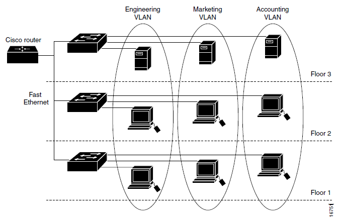
2.6 Static Route and RIP (Routing Information Protocol)Static Route is a permanent routing mechanism. The path to a network on a router device is determined directly by the administrator. In the static route setting of a router, it is the next hop when it goes to a network. RIP is a dynamic route, which is a routing mechanism that varies with time and is flexible. RIP adopts a distance-vector protocol where each router will provide information to neighboring routers about the path connected to the router. From this the router will estimate the distance of all the paths to reach other networks. After that the router will determine its own path based on the shortest distance according to router estimates from the results of exchanging information between neighboring routers (Stallings, 1998). 2.7 NAT (Network Address Translation)IPV4 is running low, meaning that most of it is already in use around the world. Therefore IPV6 was developed. While waiting for IPV6 to be implemented there is a solution to save IP addresses in version 4, namely NAT. IPV4 addresses are classified into 2 types, namely private IP and global IP. Global IP is an IP address that is only owned by 1 device worldwide and is known in the Internet network. Meanwhile, private IP is an unknown IP address on the Internet network and is free to use by any device so that the owner can be more than 1. The private IP is 10.x.x.x 255.0.0.0, 172.16.x.x 255.255.0.0, and 192.168.x.x 255.255.255.0. Whereas 127.x.x.x 255.0.0.0 is used as the loopback. In addition, it is a global IP address (Inixindo, 2005). NAT works by translating private IP to global IP and vice versa. For example a host array has private IP 192.168.10.2 - 192.168.10.254 255.255.255.0 and exits via router, gateway 192.168.10.1 255.255.255.0 which can NAT with global IP 202.130.0.5 255.255.255.0, for example to Google DNS 8.8.8.8 255.0.0.0. Then packets out of 192.168.10.2 - 192.168.10.254 will be translated to 202.130.0.5 before sending to 8.8.8.8. After that 8.8.8.8 will reply with the destination IP address 202.130.0.5, after which the router converts to the destination IP address to 192.168.10.x, depending on the sender (Peterson, 2003). 2.8 TelnetTelnet is an application that works at OSI layer 7, which is an application that can perform remote login, which is entering a device using another computer. Telnet is very useful for remote work, which should come to the location of the device to enter the system, with telnet entry to the system can be done remotely. Telnet transmits data without encryption and is opened on port number 23 (Burgess, 2004). Chapter 3 Configuration of the Badung Regency Government ICT Network3.1 IntroductionThe ICT network configuration in this report is the ICT configuration in the Badung Regency Government. ICT network configuration includes IP address addressing, VLAN identity allocation, debugging, routing, remote login, and NAT. The port usage on the device is also determined. The physical form of the configured tools can be seen in section 3.3 Tools and Materials in Figure 3.1 and Figure 3.2. IP addressing, port used, and VLAN can be seen in section 3.4 Configuration Plan. 3.2 Place and timeThe configuration was carried out in Building 10, namely the Central Government of Badung Regency Transportation and Information Agency from 4 September 2012 to 8 September 2012. 3.3 Tools and Materials
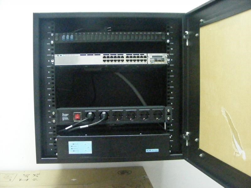
3.4 Configuration Plan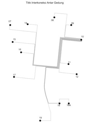 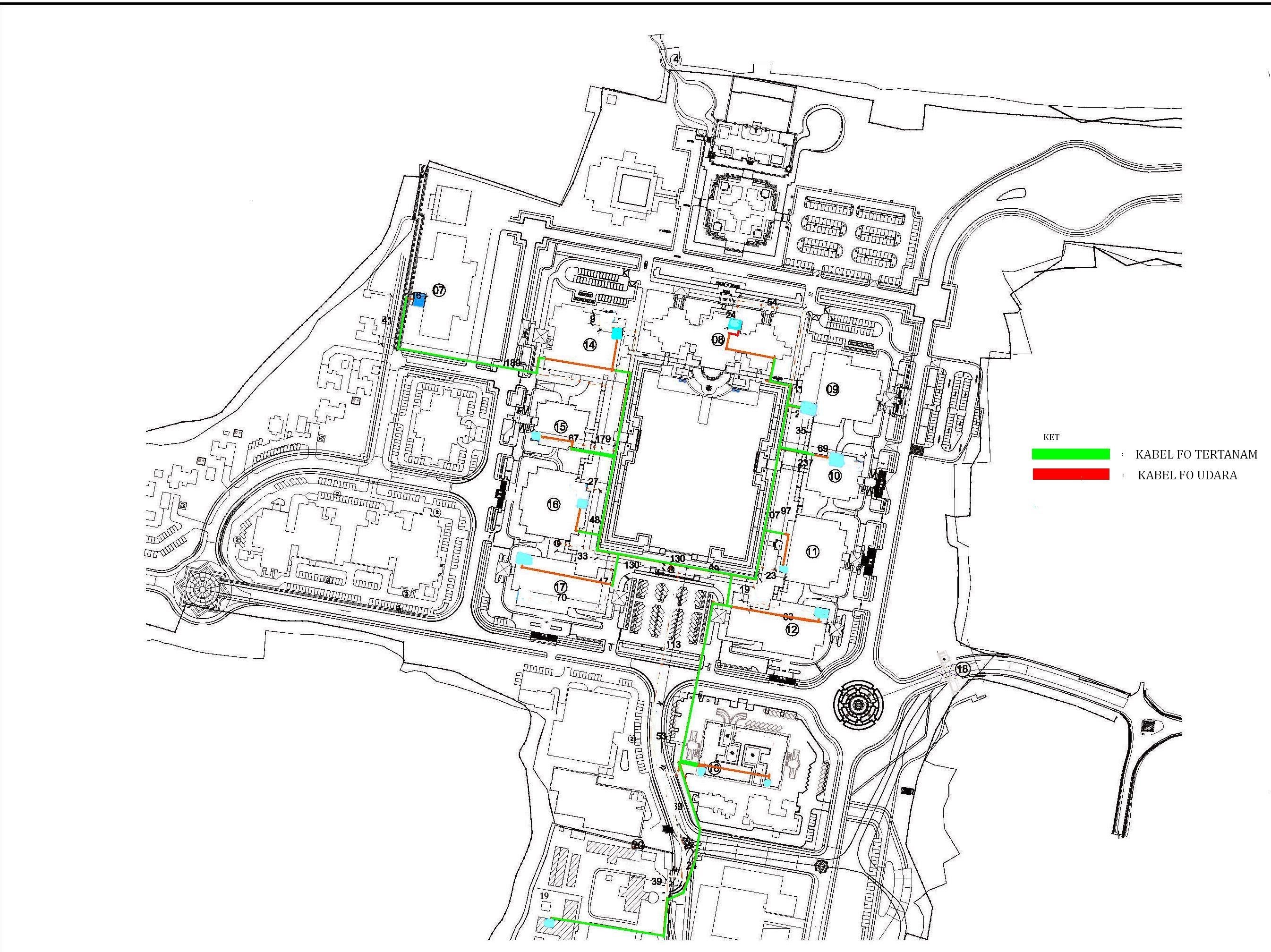
Chapter 4 Discussion4.1 IntroductionIn the discussion, a simulation of ICT modeling and configuration was carried out at the Office of Communications and Information Technology, Badung Regency Government with the Cisco Packet Tracer program. A simulation was conducted because the ICT configuration in the Badung Regency Government was fixed and not allowed to be reconfigured or further configured. Therefore, the configuration stage is simulated in the Cisco Packet Tracer program, this program is used because the tool used is Cisco. The ICT configuration in the simulation is exactly the same as the ICT configuration in the field. There are only differences in the model of the tool as described in Chapter 1 section 1.5 Scope and Boundaries, and differences in interfaces. In Section 4.2 Modem Setup is a public IP modeling where only certain IP addresses can be connected. In Section 4.3 Network Configuration Towards the Internet is the ICT configuration stage from Cisco Multilayer Switches to Modems. In section 4.4 NAT configuration is a configuration for converting local IP addresses to public IP addresses. In Section 4.5, Local Network Configuration is the configuration of Cisco Multilayer Switches to Cisco Switches in each Building. Section 4.6 Connection Test is a connection test using the ping application. 4.2 Modem SetupThe discussion of network configuration will be explained at the same time in the Cisco Packet Tracer simulation. First make a network topology. Starting from the modem configured IP address on the modem (although the modem is not a Cisco device, but its configuration is made close to its original function). According to table 3.5, the IP address at the entrance to the modem is 202.46.10.129/24. Routing used by all routers is RIP (Routing Information Protocol) version 2. The spanning-tree has been configured automatically, namely PVST. 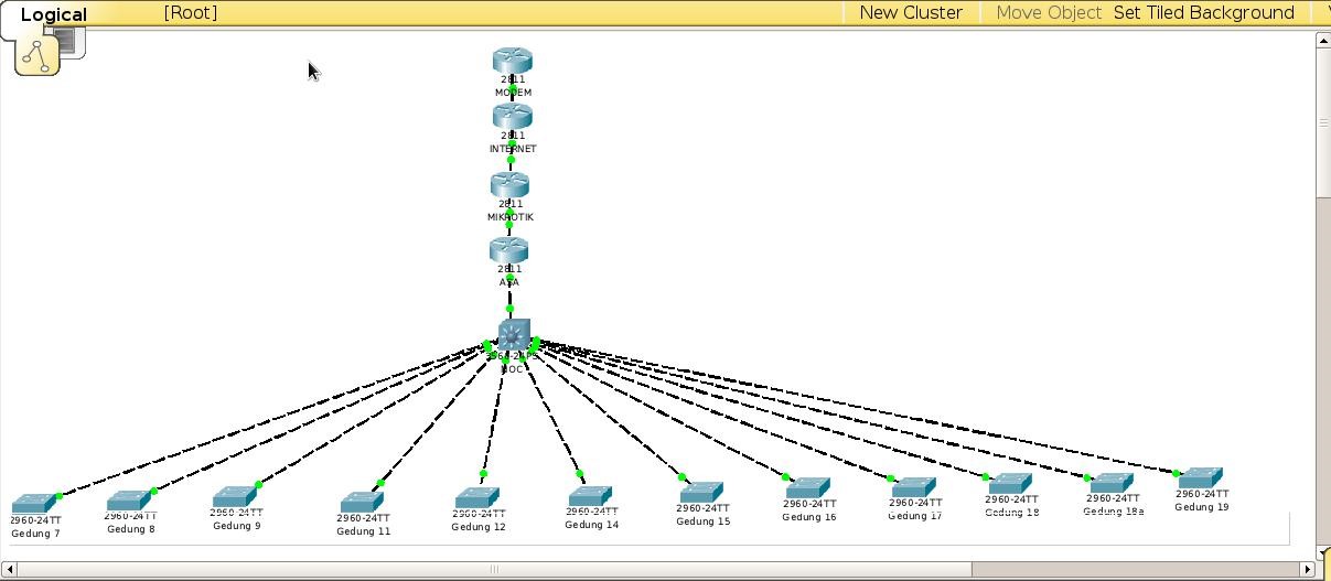
4.3 Network Configuration Towards the InternetNext, configure the Internet router. According to table 3.5, the Internet interface to the modem with the IP address is 202.46.10.130/24 (in the fastethernet interface simulation 0/1), while the interface from the Internet to Mikrotik has an IP address of 192.168.253.2/24 (in the fastethernet interface simulation 0/0). The configuration method is the same as giving an IP address to the modem, but does not do an "access-list". 
This report does not discuss the proxy configuration, therefore in this simulation how to configure a router called Mikrotik is the same as a router configuration called Internet. According to table 3.5 the interface to the Internet (fastEthernet 0/1) is assigned the IP address 192.168.253.1/24. In a connection, for example, between the Internet and Mikrotik interfaces must be on the same network ID. 192.168.253.1/24 (from Mikrotik) and 192.168.253.2/24 (from the Internet), according to Sutanta in theory, the IP address in Chapter 2 is on the same network ID, namely 192.168.253.0/24. The interface to ASA has the IP address 192.168.101.2/24. RIPv2 is "network 192.168.253.0" and "network 192.168.101.0". Cisco ASA is a device for firewalls. This report does not discuss data security, therefore in this simulation the Cisco ASA configuration method is the same as the Internet Router configuration. According to table 3.5 the interface to Mikrotik has an IP address of 192.168.101.1/24, according to Sutanta 192.168.101.2/24 and 192.168.101.1/24 are on the same network, namely 192.168.101.0/24. The interface to the NOC (Cisco multilayer switch cat4500e in the field) has an IP address of 172.16.128.2/24. RIPv2 is "network 192.168.101.0" and "network 172.16.0.0". "Network 172.16.0.0" is used because according to table 3.4 NOC will have IP networks of 172.16.0.0/24, 172.16.16.10.0/24 - 172.16.35.0/24, and 172.16.128.0/24. Therefore RIPv2 "Network 172.16.0.0" will deal with IP addresses 172.16.0.0 - 172.16.255.255. How to configure Internet routers in Multilayer Switch NOC (Cisco Multilayer Switch cat4500e in the field). There is a slight difference. By default, all NOC interfaces on the NOC function as switches.
4.4 Configure NAT (Network Address Translation) on the Cisco Router 2900
Based on all the above configurations it is not enough to connect from NOC to Modem. NOC to ASA, Mikrotik, and the Internet can be connected but not to the Modem. In fact, only the IP address 202.46.10.130 can be entered in the field. 
According to table 3.5 there are 2 public IPs, namely on the Internet and Modem. In order to connect to the modem, the incoming IP address must be converted to 202.46.10.130. 
4.5 Local Network ConfigurationThe last configuration is on the LAN (Local Area Network), which is the configuration connecting all Cisco c3700e switches in all buildings to the Multilayer Switch cat4500e in building 10 (NOC). Providing VLAN identity per building and per service based on table 3.3. In this configuration, the interface of each VLAN in the NOC is made with an IP address based on table 3.4 and the table provides information on VLAN installation on several interfaces on the switch of each building. For how to configure the switches for each building is the same. So at this writing the local NOC configuration will be displayed and only 2 switch configurations from 2 buildings. 
Depending on the device, the “VLAN database” command can be configured before the configure terminal or at the configure terminal, this command will enter VLAN settings. After that, enter the command "vlan 10" to add VLAN 10. Adding VLANs is done according to table 3.3 and table 3.4, adding VLAN 10 - VLAN 35. 
Assigning an IP address to the VLAN 1 interface is a way to assign an IP address to a device. According to table 3.3 the IP address on the NOC is 172.16.0.10/24. The command "interface range fastEthernet 0/1 - 12" is a way to enter fastethernet 0/1 - fastethernet 0/12 at once. It was planned on this interface (connected to the switch of each building) so that all VLAN IDs can pass. So the command is "switchport mode trunk", there is a switch that must be given the command "switchport trunk encapsulation dot1Q", which is an IEEE (Intitute Electrical Electronic Engineer) 802.1Q standard, for VLAN standards. According to table 3.4 VLAN interfaces 10-35 are assigned an IP address. 
The initial line is a general configuration performed on all devices, namely, service timestamps, service password-encryption, line vty 0 4 (telnet login), secret installation (MD5 password), installation on the VLAN interface 1. Gigabitethernet 1/1 interface is the interface that connected to the NOC. So that all VLANs can enter, then with the command "switchport mode trunk". Based on table 3.4, the fastethernet 0 / 1-4 interface is given the entry of only VLAN 10 with the commands "interface range fastethernet 0/1 - 4", "switchport mode access", and "switchport access vlan 10". In this simulation, so that VLAN 1 in each building is connected, each switch is given a default-gateway with the command "ip default-gateway 172.16.0.10", which is the default route to VLAN 1 NOC. 
Next is configuration on the Switch Building 12. The method is the same as Building 7, according to tables 3.3 and 3.4 VLAN 18-20 is installed. For other switch configurations, the method is the same. Then the configuration is complete, to see the configuration results you can type the command "show running-config". 
4.6 Testing ConnectionAt this writing only a few tests were written. First, the computer is installed on the Building 7 switch on the fastethernet0/1 interface. After that configured and ping the interface VLAN 10 and Modem. After that, telnet to the NOC and switch Building 12. 
Chapter 5 Closing5.1 ConclusionThe topology on this network is a tree. The local network consists of 12 switches and 1 multilayer switch. All buildings are connected to building 10. Each office is on 1 VLAN ID. The total VLAN used is 25 of VLAN 10 - Vlan 35, with a network ID of 172.16.10.0/24-172.16.35.0/24. Installation of a VLAN ID is carried out in 1 multilayer switch in 10 buildings and 12 switches in all buildings. The port that is connected from 12 switches to a multilayer switch is a trunk mode where all VLAN IDs can enter. Each switch and multilayer switch is assigned an IP address on VLAN 1 as if it were assigned an IP address on the device. From the multilayer switch to the Internet network must pass through ASA, Mikrotik, Router, and Modem. The multilayer switch port to the Internet network functions as a router so that the switchport mode is turned off and assigned an IP address. After that the routing mode is activated, static routing is used for the Internet network, while for the internal use RIPv2 dynamic routing. Likewise in ASA, Mikrotik, and Router. The router is given 1 public IP. Everything that goes to the router goes to the modem, then to the Internet network, the private IP address is converted into a public IP with NAT. For the purpose of processing all devices enabled log and debug for notification of changes in the device. Secret and password are activated for telnet purposes. Telnet server is activated so that you can remote login. 5.2 SuggestionsThe suggestion that can be given is to improve the quality of the network configuration.
Bibliography
Content CreationBlogs
Videos
Images
Personal Monetization
Common TasksBrowsing
Cointiply
ReferralsCurrently the quantity is too much to handle when the value I earned is not much. So I may report this on a separate article. October 2020 Income ≈ $142Grade: CPersonnal Comments
Appendix


DonationPersonally, I enjoyed being a full time independent content creator very much and I do not mind to continue much longer but I have families and friends pressuring me for result and if I do not show a satisfying one, then I have to get employed like everyone else which means spends much less time in this work. Therefore, I once again thank the platforms, investors, donators, and viewers for making my venture possible through donations, tippings, and upvotes. If you enjoy and/or want to further support my work you may choose a from of donation:

Mirror
Catatan
AbstrakProyek Instalasi Fiber Optik di Kawasan Pusat Pemerintah Kabupaten Badung merupakan suatu cara untuk beralih ke berbasis ICT (Information Communication Technology). Pelaksanaan proyek dilaksanakan dengan survei lingkungan, penyiapan alat, bahan, dan tenaga kerja, pembuatan jalur fiber optik, penamaman fiber optik, penghubungan fiber optik ke perangkat di masing-masing gedung, konfigurasi jaringan, dan perapian tepat menjadi seperti semula. Pada laporan ini akan dibahas mengenai konfigurasi jaringan. Yang perlu dipahami untuk melakukan konfigurasi ini adalah pemahaman penggunaan perangkat, pemahaman mengenai alamat IP, pemahaman VLAN (Virtual Local Area Network), pemahaman static route dan RIP (Routing Information Protocol), remote login, dan NAT (Network Address Translation). Konfigurasi dilakukan di Gedung 10 yaitu Dinas Perhubungan Komunikasi dan Informatika Pusat Pemerintah Kabupaten Badung pada tanggal 4 September 2012 hingga 8 September 2012. Alat yang diperlukan untuk melakukan konfigurasi adalah laptop, kabel UTP, kabel DB9M-USB converter, dan kabel console Cisco. Software yang dibutuhkan untuk konfigurasi adalah serial terminal dan telnet client. Perencanaan konfigurasi pertama adalah pemberian alokasi VLAN (Virtual Local Area Network) pada masing-masing dinas di masing-masing gedung. Kedua pemberian alokasi alamat IP pada masing-masing VLAN. Ketiga adalah pemberian alokasi alamat IP pada masing-masing perangkat. Keempat adalah pembentukan topologi. Konfigurasi pertama adalah pada jaringan lokal. Pemberian alamat IP masing-masing switch adalah pada VLAN 1. Masing-masing switch diberikan VLAN ID berdasarkan dinas yang terdapat pada gedung tersebut. Koneksi dari switch ke multilayer switch diberi mode trunk agar semua VLAN ID bisa lewat. Pada multilayer switch port yang terkoneksi ke jaringan Internet diberi alamat IP dan pada multilayer switch diberi konfigurasi routing. Routing juga diatur pada router lainnya. Pada Router 2900 dikonfigurasi NAT (Network Address Translation) untuk menerjemahkan alamat IP lokal dari dalam menjadi alamat IP Public menuju keluar. Semua perangkat diaktifkan debug, log, dan Telnet login. Pada konfigurasi alamat IP disini terjadi pemborosan alamat IP. Disarankan untuk mengkonfigurasi ulang subnet mask. Disarankan lagi untuk lebih banyak memberi label pada port dan VLAN ID untuk mempermudah management. Keywords: Wireless Sensor Network, Imote2, Embedded Linux, ZigBee, WLAN, JTAG, OpenOCD. BAB 1 Pendahuluan1.1 Latar BelakangICT (Information Communication Technology) merupaka suatu istilah yang mencangkup mengenai informasi, komunikasi, telekomunikasi, dan komputer. Dengan adanya ICT ini menggantikan tempat informasi yang bersifat benda nyata. Perpustakaan dapat diganti dengan halaman web pada jaringan Internet, dokumen berupa kertas dan buku dapat diganti dengan server berisi dokumen elektronik, surat-menyurat melewati pos dapat diganti dengan email (electronic mail). Pada Internet tersedia juga informasi berupa gambar dan video. Keuntungan metode ini dibanding dengan metode klasik adalah efisiensi terhadap energi, tempat, dan waktu. Dengan ICT ini segala bentuk informasi yang terkandung dapat diakses kapan saja dan dimana saja secara cepat (tanpa harus membuang energi dan waktu untuk pergi ke suatu tempat dan dibatasi oleh waktu untuk mengakses suatu informasi). Banyak Pusat Pemerintah yang beralih ke berbasis ICT, artinya mulai memanfaatkan teknologi ICT untuk kepentingan Pemerintah. Salah satu contoh pengiriman dokumen lewat post atau pengiriman dokumen dengan mendatangi tujuan pengiriman secara langsung mulai diganti dengan email. Tempat dimana penulis dilakukan kerja praktek yaitu di Pusat Pemerintah Kabupaten Badung telah beralih ke berbasis ICT. Kerja Praktek di Pusat Pemerintah Kabupaten Badung adalah menjalankan Proyek Instalasi Fiber Optik di seluruh Dinas yang ada di Pusat Pemerintah Kabupaten Badung. Pemilik Proyek adalah Dishubkominfo (Dinas Perhubungan, Komunikasi dan Informatika) Pemerintah Kabupaten Badung, pelaksana adalah PT. Skill Surabaya, dan pengawas adalah CV. Bali Info Data. Penulis berada di pihak pengawas. Dari semua tahap Pembangunan Infrastruktur Jaringan Fiber Optik Di Kawasan Pusat Pemerintah Kabupaten Badung , pada Laporan Kerja Praktek ini khusus pada tahap konfigurasi ICT. Agar lebih mudah untuk diserap, konfigurasi jaringan komputer ini akan di simulasikan pada program simulator jaringan Cisco Packet Tracer. Dilakukan simulasi karena penulis berada di pihak pengawas, sehingga tidak dapat diperlihatkan tahap-tahap konfigurasi secara langsung, dikarenakan konfigurasi ICT di Pemerintah Kabupaten Badung bersifat tetap, tidak diperbolehkan untuk konfigurasi ulang. Digunakannya program ini karena alat yang digunakan hampir semua merupakan barang Cisco. 1.2 TujuanMelaporkan konfigurasi jaringan komputer pada Proyek Pembangunan Infrastruktur Jaringan Fiber Optik di Kawasan Pusat Pemerintah Kabupaten Badung, dan mensimulasikannya di Cisco Packet Tracer. 1.3 Manfaat
1.4 Pelaksanaan Kerja PraktekKerja Praktek ini adalah Pembangunan Infrastruktur Jaringan Fiber Optik dilaksanakan dari Juni-September 2013 di Kawasan Pusat Pemerintah Kabupaten Badung. Secara umum tahap proyek ini adalah
1.5 Ruang Lingkup dan Batasan
1.6 Sistematika Penulisan
BAB 2 Tinjauan Pustaka2.1 PendahuluanUntuk melakukan konfigurasi ini diperlukan pengetahuan mengenai saat menggunakan kabel ethernet RJ45 tipe straight-thru atau crossover untuk menghubungkan antar perangkat. Pada konfigurasi ICT ini digunakan switch sebagai penghubung antar banyak perangkat dan router sebagai penghubung ke Internet. Pengalamatan perangkat digunakan IPV4 (Internet Protocol Version 4). Diperlukan pengetahuan yang dalam mengenai IPV4 untuk konfigurasi ICT tingkat seluas pusat Pemerintah. Diperlukan pengetahuan mengenai VLAN (Virtual Local Area Network) untuk memudahkan management jaringan lokal, dan sedikit NAT (Network Address Translation) untuk menghubungkan ke Internet. Telnet login bersifat optional, untuk memudahkan management. Maka teori-teori yang perlu diketahui dijelaskan pada BAB ini. 2.2 Kabel Ethernet RJ45 dan Kabel DB9 - RJ45Kabel Ethernet RJ45 yang menghubungkan komputer dengan switch, switch dengan router menggunakan kabel straight-thru. Sedangkan untuk menghubungkan antar komputer, antar switch, antar router, dan komputer dengan router menggunakan kabel crossover. Kabel ethernet RJ45 terdiri dari 8 pin, dimana 4 yang digunakan sebagai transmitter tegangan minus, transmitter tegangan plus, receiver minus, dan receiver plus. Ada jenis straight-thru dan crossover karena terdapat perbedaan lokasi transmitter dan receiver (The Internet Center, 2013).
Kabel console Cisco digunakan untuk mengkonfigurasi perangkat Cisco. Kabel ini merupakan DB9 female ke RJ45 male.
2.3 Switch dan RouterSwitch merupakan sebuah perangkat yang dapat menghubung antar komputer, antar jaringan lokal, dan antar komputer dengan jaringan lokal. Pada OSI (Open Systems Interconnection) reference model bekerja pada layer 2 yaitu datalink. Switch memiliki beberapa port dan bekerja dengan melanjutkan frame yang datang dari suatu port ke port yang dituju. Switch menyimpan hardware address dan tempat port yang terhubung perangkat-perangkat yang terhubung di suatu port. Router merupakan sebuah perangkat yang menghubungkan antar jaringan (saat ini antar switch). Pada OSI (Open Systems Interconnection) reference model bekerja pada layer 3 yaitu network. Router bekerja berdasarkan network address. Router menentukan jalur untuk menuju jaringan lain (Gebali, 2008). 2.4 IP (Internet Protocol) AddressIP adress atau di terjemahkan sebagai alamat IP mendefinisikan sebuah host atau sebuah router ke jaringan Internet, merupakan deretan angka biner. Pada jaringan komputer dan jaringan Internet saat ini menggunakan IP address untuk menunjukkan identitas sebuah perangkat. Alamat ini yang digunakan sebagai identitas pengirim dan penerima data. Oleh karena itu IP address harus unik dan universal. Saat ini ada 2 versi IP, yaitu IP versi 4 dan IP versi 6. IPV4 terdiri dari 32 bit dan ditulis dalam bentuk biner atau decimal, sedangkan IPV6 terdiri dari 128 bit dan ditulis dalam bentuk biner atau hexadecimal, yang saat ini digunakan adalah IPV4, IPV6 untuk masa depan. IPV4 ditulis dengan subnet mask atau prefix. Penulisannya secara desimal dibagi per byte atau 8 bit (xxxxxxxx.xxxxxxx.xxxxxxx.xxxxxxx). Contoh 2.1 Sebuah alamat IP 192.168.0.1 (11000000.10101000.00000000.00000001) 255.255.255.0 (11111111.1111111.1111111.00000000). Penulisan secara prefixnya adalah 192.168.0.1/24 (x.x.x.x/n), angka 24 menyatakan jumlah bit 1 dalam subnet mask. Oleh karena itu penulis subnet mask hanya boleh terbagi 2 kutub, yaitu bagian kiri angka 1, dan bagian kanan angka 0 (tidak bisa acak). Subnet mask menunjukkan jumlah host dalam suatu jaringan, menunjukkan network ID (identity), dan host ID. Untuk mencari network ID suatu alamat IP yaitu dengan melakukan operasi AND terhadap subnet mask yang diberikan. Contoh 2.2 Dari contoh 2.1 192.168.0.1 (11000000.10101000.00000000.00000001) 255.255.255.0 (11111111.1111111.1111111.00000000), maka jika 11000000.10101000.00000000.00000001 AND 11111111.1111111.1111111.00000000 hasilnya adalah 11000000.10101000.00000000.00000000 yaitu 192.168.0.0 merupakan network ID, dengan identitas host 192.168.0.1. IP address bisa berupa class atau classless. Bila berupa class maka dibagi atas 5 kelas, yaitu A, B, C, D, dan E. Yang digunakan secara umum adalah A – C, sedangkan D untuk multicast dan E secara experimental, dan digunakan untuk keperluan masa depan (Sutanta, 2005). Berikut adalah 2 tabel yang menunjukkan kelas dan tabel mengenai prefix.
Jika subnet mask diperdalam, maka subnet mask dapat menentukan jumlah IP address pada suatu network. Jumlah IP address dapat dihitung dari bit 1 sebelah kanan digabung dengan semua bit 0 yang ada pada subnet mask. Contoh 2.3 255.255.255.0 (11111111.1111111.1111111.00000000), maka jumlah alamat IP = 10000000(2) yaitu 256(10), 255.255.255.224 (11111111.1111111.11111111.11100000), maka jumlah alamat IP = 100000(2) yaitu 32(10). Dari semua alamat IP dalam suatu jaringan IP address pertama dipakai sebagai network ID, IP address terkahir dipakai sebagai broadcast ID, dan bila merupakan jaringan WAN (Wide Area Network) diperlukan 1 IP address lagi sebagai gateway (menuju jaringan lain) biasanya dipasang setelah network ID. Contoh 2.4 192.168.0.1 (11000000.10101000.00000000.00000001) 255.255.255.0 (11111111.1111111.1111111.00000000), maka jika 11000000.10101000.00000000.00000001 AND 11111111.1111111.1111111.00000000 hasilnya adalah 11000000.10101000.00000000.00000000 yaitu 192.168.0.0 merupakan network ID, dengan identitas host 192.168.0.1, dengan subnet mask 255.255.255.0 (11111111.1111111.1111111.00000000), maka jumlah IP addresss keseluruhan adalah 10000000(2) = 256(10), alamat pertama 192.168.0.0 sebagai network ID dan alamat terakhir adalah 192.168.0.255 sebagai broadcast ID, dan bisa dipilih dari 192.168.0.1 – 192.168.0.254 sebagai gateway, dan sisanya bisa dipakai untuk host (Inixindo, 2005). Untuk lebih didalami dapat dilihat tabel berikut.
Kesimpulannya semakin sedikit jumlah bit 1 pada subnet mask semakin banyak jumlah host dan semakin sedikit jumlah network ID, dan sebaliknya. 2.5 VLAN (Virtual Local Area Network)VLAN merupakan sekumpulan perangkat pada 1 atau lebih LAN yang terkonfigurasi untuk berkomunikasi bagaikan terhubung pada kabel yang sama, dimana sebenarnya mereka berada pada segment LAN yang berbeda. Vlan berdasarkan logika dari pada fisik, oleh karena VLAN fleksibel. VLAN mendefinisikan broadcast domain pada layer 2. Broadcast domain merupakan sekumpulan perangkat yang akan menerima broadcast frames dari perangkat manapun. Layer 2 Switches membikin broadcast domain berdasarkan konfigurasi switch. Switch merupakan multiport bridges yang dapat membuat banyak broadcast domain. Satu VLAN dapat merupaka satu broadcast domain. VLAN satu antara lainnya tidak dapat saling berhubungan karena berada pada broadcast domain yang berbeda. Untuk menghubungkan antar VLAN perlu menggunakan router atau layer 3 switch (Cisco, 2004).
2.6 Static Route dan RIP (Routing Information Protocol)Static Route merupakan mekanisme routing yang permanen. Jalur untuk menuju suatu jaringan pada sebuah perangkat router ditentukan langsung oleh administrator. Pada pengaturan static route suatu router adalah next hop (jalur berikutnya) bila menuju suatu jaringan. RIP merupakan salah satu dynamic route yaitu mekanisme routing yang berubah-ubah terhadap waktu dan bersifat fleksibel. RIP mengadopsi distance-vector protocol dimana masing-masing router akan memberikan informasi ke router tetangga mengenai jalur yang terhubung pada router tersebut. Dari hal tersebut router akan mengestimasi jarak semua jalur untuk mencapai jaringan lainnya. Setelah itu router akan menentukan sendiri jalurnya berdasarkan jarak terpendek menurut estimasi router dari hasil pertukaran informasi antar router tetangga (Stallings, 1998). 2.7 NAT (Network Address Translation)IPV4 sudah hampir habis, artinya sebagian besar sudah digunakan diseluruh dunia. Oleh karena itu dikembangkan IPV6. Selama menunggu IPV6 diterapkan ada solusi untuk menghemat alamat IP pada versi 4 yaitu NAT. Alamat IPV4 digolongkan 2 jenis yaitu IP privat dan IP global. IP global merupakan alamat IP yang hanya dimiliki 1 perangkat diseluruh dunia dan dikenal dalam jaringan Internet. Sedangkan IP privat merupakan alamat IP yang tidak dikenal dalam jaringan Internet dan bebas digunakan oleh perangkat manapun sehingga pemilik lebih dari 1. IP privat adalah 10.x.x.x 255.0.0.0, 172.16.x.x 255.255.0.0, dan 192.168.x.x 255.255.255.0. Sedangkan 127.x.x.x 255.0.0.0 digunakan sebagai loopback. Selain itu merupakan alamat IP global (Inixindo, 2005). NAT bekerja dengan menerjemahkan IP privat menjadi IP global dan sebaliknya. Misalnya sederetan host memiliki IP privat 192.168.10.2 – 192.168.10.254 255.255.255.0 dan keluar melewati router, gateway 192.168.10.1 255.255.255.0 yang dapat melakukan NAT dengan IP global 202.130.0.5 255.255.255.0, misalnya ke DNS Google 8.8.8.8 255.0.0.0. Maka paket keluar dari 192.168.10.2 – 192.168.10.254 akan diterjemahkan menjadi 202.130.0.5 sebelum terkirim ke 8.8.8.8. Setelah itu 8.8.8.8 akan membalasnya dengan alamat IP tujuan 202.130.0.5, setelah itu router mengkonversi ke alamat IP tujuan menjadi 192.168.10.x, tergantung pengirim (Peterson, 2003). 2.8 TelnetTelnet merupakan applikasi bekerja pada OSI layer 7 yaitu applikasi yang dapat melakukan remote login yaitu masuk ke suatu perangkat menggunakan komputer lain. Telnet sangat berguna untuk bekerja jarak jauh, yang seharusnya datang ke lokasi perangkat untuk masuk ke sistem, dengan telnet pemasukan ke sistem dapat dilakukan jarak jauh. Telnet mentransmisikan data tanpa enkripsi dan dibuka pada port nomor 23 (Burgess, 2004). BAB III Konfigurasi Jaringan ICT Pemerintah Kabupaten Badung3.1 PendahuluanKonfigurasi jaringan ICT pada laporan ini adalah konfigurasi ICT di Pemerintah Kabupaten Badung. Konfigurasi jaringan ICT meliputi pengalamatan IP address, pengalokasian identitas VLAN, debugging, routing, remote login, dan NAT. Pemakaian port pada perangkat juga ditentukan. Bentuk fisik alat yang dikonfigurasi dapat dilihat pada subbab 3.3 Alat dan Bahan pada Gambar 3.1 dan Gambar 3.2. Pengalamatan IP, port yang digunakan, dan VLAN dapat dilihat pada subbab 3.4 Rencana Konfigurasi. 3.2 Tempat dan WaktuKonfigurasi dilakukan di Gedung 10 yaitu Dinas Perhubungan Komunikasi dan Informatika Pusat Pemerintah Kabupaten Badung pada tanggal 4 September 2013 hingga 8 September 2013. 3.3 Alat dan Bahan
3.4 Recanan Konfigurasi
BAB 4 Pembahasan4.1 PendahuluanPada pembahasan dilakukan simulasi pemodelan dan konfigurasi ICT di Dinas Perhubungan Komunikasi dan Informatika, Pemerintah Kabupaten Badung dengan program Cisco Packet Tracer. Dilakukan simulasi karena konfigurasi ICT di Pemerintah Kabupaten Badung bersifat tetap dan tidak diperbolehkan untuk dikonfigurasi ulang atau dikonfigurasi lanjut. Oleh karena itu tahap konfigurasi disimulasikan di program Cisco Packet Tracer, digunakan program ini karena alat yang digunakan adalah Cisco. Konfigurasi ICT pada simulasi sama persis dengan konfigurasi ICT di lapangan. Hanya terdapat perbedaan pada model alat seperti dijelaskan pada BAB I subbab 1.5 Ruang Lingkup dan Batasan, dan perbedaan pada interface. Pada subbab 4.2 Penyiapan Modem adalah pemodelan IP public dimana hanya alamat IP tertentu yang dapat terkoneksi. Pada subbab 4.3 Konfigurasi Jaringan Menuju Internet adalah tahap konfigurasi ICT dari alat Cisco Multilayer Switch sampai Modem. Pada subbab 4.4 Konfigurasi NAT adalah konfigurasi konversi alamat IP lokal ke alamat IP publik. Pada subbab 4.5 Konfigurasi Jaringan Lokal adalah konfigurasi dari alat Cisco Multilayer Switch ke Cisco Switch di masing-masing Gedung. Subbab 4.6 Tes Koneksi adalah pengujian koneksi menggunakan aplikasi ping. 4.2 Penyiapan ModemPembahasan konfigurasi jaringan akan sekaligus dijelaskan pada simulasi Cisco Packet Tracer. Pertama dibuat topologi jaringan. Mulai dari modem dikonfigurasi alamat IP di modem (walaupun modem bukan perangkat cisco, tetapi dibikin konfigurasinya mendekati dengan fungsi aslinya). Berdasarkan tabel 3.5, alamat IP digerbang masuk modem adalah 202.46.10.129/24. Routing yang digunakan seluruh router adalah RIP (Routing Information Protocol) versi 2. Spanning-tree telah terkonfigurasi secara automatis yaitu PVST.
4.3 Konfigurasi Jaringan Menuju InternetSelanjutnya konfigurasi router Internet. Menurut tabel 3.5 interface Internet menuju Modem dengan alamat IP 202.46.10.130/24 (di simulasi interface fastethernet 0/1), sedangkan interface dari Internet ke Mikrotik memiliki alamat IP 192.168.253.2/24 (di simulasi interface fastethernet 0/0). Cara konfigurasi sama seperti memberi alamat IP pada Modem, tetapi tidak melakukan “access-list”.
Pada laporan ini tidak dibahas mengenai konfigurasi mikrotik, oleh sebab itu pada simulasi ini cara konfigurasi router yang bernama mikrotik sama dengan cara konfigurasi router yang bernama Internet. Menurut tabel 3.5 interface yang menuju Internet (fastethernet 0/1) diberi alamat IP 192.168.253.1/24. Dalam suatu koneksi contohnya antara interface Internet dan Mikrotik harus berada pada network ID yang sama. 192.168.253.1/24 (dari Mikrotik) dan 192.168.253.2/24 (dari Internet), menurut Sutanta pada teori IP address di BAB 2 berada pada network ID yang sama yaitu 192.168.253.0/24. Interface menuju ASA memiliki alamat IP 192.168.101.2/24. RIPv2 adalah “network 192.168.253.0” dan “network 192.168.101.0”. Cisco ASA merupakan perangkat untuk firewall. Pada laporan ini tidak dibahas mengenai keamanan data, oleh karena itu dalam simulasi ini cara konfigurasi Cisco ASA sama dengan cara konfigurasi Router Internet. Menurut tabel 3.5 interface menuju Mikrotik memiliki alamat IP 192.168.101.1/24, menurut Sutanta 192.168.101.2/24 dan 192.168.101.1/24 berada pada jaringan yang sama yaitu 192.168.101.0/24. Interface menuju NOC (Cisco multilayer switch cat4500e dilapangan) memiliki alamat IP 172.16.128.2/24. RIPv2 adalah “network 192.168.101.0” dan “network 172.16.0.0”. “Network 172.16.0.0” digunakan karena menurut tabel 3.4 NOC akan memiliki jaringan IP 172.16.0.0/24, 172.16.16.10.0/24 – 172.16.35.0/24, dan 172.16.128.0/24. Oleh karena itu RIPv2 “Network 172.16.0.0” akan mengenai alamat IP 172.16.0.0 – 172.16.255.255. Cara konfigurasi router Internet dilakukan di Multilayer Switch NOC (Cisco Multilayer Switch cat4500e di lapangan). Terdapat sedikit perbedaan. Secara default NOC semua interface di NOC berfungsi sebagai switch.
4.4 Konfigurasi NAT (Network Address Translation) pada Cisco Router 2900
Berdasarkan semua konfigurasi diatas belum cukup untuk mengkoneksi dari NOC ke Modem. NOC menuju, ASA, Mikrotik, dan Internet dapat terkoneksi namun tidak ke Modem. Secara kenyataan dilapangan hanya alamat IP 202.46.10.130 yang bisa masuk.
Menurut tabel 3.5 terdapat 2 IP public yaitu pada Internet dan Modem. Agar dapat terkoneksi dengan Modem maka alamat IP yang masuk harus dikonversi menjadi 202.46.10.130.
4.5 Konfigurasi Jaringan LokalKonfigurasi terakhir adalah pada LAN (Local Area Network), yaitu konfigurasi menghubung semua Cisco switch c3700e di semua gedung menuju Multilayer Switch cat4500e di gedung 10 (NOC). Pemberian identitas VLAN per gedung dan per dinas berdasarkan tabel 3.3. Pada konfigurasi ini dibuat interface masing-masing VLAN di NOC dengan alamat IP berdasarkan tabel 3.4 dan pada tabel tersebut tersedia informasi pemasangan VLAN pada beberapa interface di switch masing-masing gedung. Untuk cara konfigurasi switch masing-masing gedung sama. Maka pada penulisan ini akan ditampilkan konfigurasi lokal NOC dan hanya 2 konfigurasi switch dari 2 gedung.
Tergantung perangkat, perintah “VLAN database” dapat dikonfigurasi sebelum configure terminal atau pada configure terminal, perintah ini untuk masuk ke pengaturan VLAN. Setelah itu dimasukan perintah “vlan 10” untuk menambah VLAN 10. Penambahan VLAN dilakukan berdasarkan tabel 3.3 dan tabel 3.4, penambahan VLAN 10 – VLAN 35.
Pemberian alamat IP pada interface VLAN 1 merupakan suatu cara untuk memberian alamat IP pada perangkat. Menurut tabel 3.3 alamat IP pada NOC adalah 172.16.0.10/24. Perintah “interface range fastethernet 0/1 – 12” adalah cara untuk masuk ke fastethernet 0/1 – fastethernet 0/12 sekaligus. Direncanakan pada interface tersebut (terbuhubung ke switch masing-masing gedung) agar semua ID VLAN bisa lewat. Maka perintahnya adalah “switchport mode trunk”, ada switch yang harus diberi perintah “switchport trunk encapsulation dot1Q” yaitu merupakan standar IEEE (Intitute Electrical Electronic Engineer) 802.1Q, untuk standar VLAN. Menurut tabel 3.4 interface VLAN 10-35 diberikan alamat IP.
Baris awal merupakan konfigurasi umum yang dilakukan pada semua perangkat yaitu, service timestamps, service password-encryption, line vty 0 4 (telnet login), pemasangan secret (password MD5), pemasangan pada interface VLAN 1. Interface gigabitethernet 1/1 merupakan interface yang terkoneksi dengan NOC. Agar semua VLAN bisa masuk maka dengan perintah “switchport mode trunk”. Berdasarkan tabel 3.4 interface fastethernet 0/1-4 diberikan pemasukan hanya VLAN 10 yaitu dengan perintah “inteface range fastethernet 0/1 – 4”, “switchport mode access”, dan “switchport access vlan 10”. Pada simulasi ini agar VLAN 1 pada masing – masing gedung terkoneksi maka masing-masing switch diberi default-gateway dengan perintah “ip default-gateway 172.16.0.10” yaitu default route ke VLAN 1 NOC.
Selanjutnya konfigurasi pada switch Gedung 12. Caranya sama seperti Gedung 7, menurut tabel 3.3 dan 3.4 dipasang VLAN 18-20. Untuk konfigurasi switch yang lain caranya sama. Maka konfigurasi selesai, untuk melihat hasil konfigurasi dapat mengetik perintah “show running-config”.
4.6 Pengujian KoneksiPada penulisan ini hanya ditulis beberapa pengujian. Pertama dipasang komputer pada switch Gedung 7 pada interface fastethernet0/1. Setelah itu dikonfigurasi dan melakukan ping ke interface VLAN 10 dan Modem. Setelah itu telnet ke NOC dan switch Gedung 12.
BAB 5 Penutup5.1 SimpulanTopologi pada jaringan ini adalah tree. Pada jaringan lokal terdiri dari 12 switch dan 1 multilayer switch. Semua gedung terkoneksi ke gedung 10. Masing-masing dinas berada pada 1 VLAN ID. Total VLAN yang digunakan adalah 25 dari VLAN 10 – Vlan 35, dengan network ID 172.16.10.0/24-172.16.35.0/24. Pemasangan suatu VLAN ID dilakukan di 1 multilayer switch di gedung 10 dan 12 switch semua gedung. Port yang terkoneksi dari 12 switch ke multilayer switch adalah mode trunk dimana agar semua VLAN ID bisa masuk. Masing-masing switch dan multilayer switch diberi alamat IP pada VLAN 1 seolah-olah pemberian alamat IP pada perangkat tersebut. Dari multilayer switch menuju jaringan Internet harus melewati ASA, Mikrotik, Router, dan Modem. Port multilayer switch menuju jaringan Internet berfungsi sebagai router sehingga mode switchport dimatikan dan diberi alamat IP. Setelah itu mode routing diaktifkan, untuk ke jaringan Internet menggunakan static routing sedangkan untuk intern digunakan dynamic routing RIPv2. Begitu juga di ASA, Mikrotik, dan Router. Pada Router diberi 1 IP public. Semua yang masuk ke Router menuju modem, lalu ke jaringan Internet, alamat IP private di konversi menjadi IP public dengan NAT. Untuk kepentingan pengolahan semua perangkat diaktifkan log dan debug untuk pemberitahuan jika ada perubahana pada perangkat. Secret dan password diaktfikan untuk kepentingan telnet. Telnet server diaktifkan agar dapat remote login. 5.2 SaranSaran yang dapat disampaikan adalah untuk meningkatkan kualitas dari konfigurasi jaringan.
Daftar Pustaka
|
Archives
August 2022
Categories
All
source code
old source code Get any amount of 0FP0EXP tokens to stop automatic JavaScript Mining or get 10 0FP0EXP tokens to remove this completely. get 30 0FP0EXP Token to remove this paypal donation. get 20 0FP0EXP Token to remove my personal ADS. Get 50 0FP0EXP Token to remove my NFTS advertisements! |
||||||||||||||||||||||||||||||||||||||||||||||||||||||||||||||||||||||||||||||||||||||||||||||||||||||||||||||||||||||||||||||||||||||||||||||||||||||||||||||||||||||||||||||||||||||||||||||||||||||||||||||||||||||||||||||||||||||||||||||||||||||||||||||||||||||||||||||||||||||||||||||||||||||||||||||||||||||||||||||||||||||||||||||||||||||||||||||||||||||||||||||||||||||||||||||||||||||||||||||||||||||||||||||||||||||||||||||||||||||||||||||||||||||||||||||||||||||||||||||||||||||||||||||||||||||||||||||||||||||||||||||||||||||||||||||||||||||||||||||||||||||||||||||||||||||||||||||||||||||||||||||||||||||||||||||||||||||||||||||||||||||||||||||||||||||||||||||||||||||||||||||||||||||||||||||||||||||||||||||||||||||||||||||||||||||||||||||||||||||||||||||||||||||||||||||||||||||||||||||||||||||||||||||||||||||||||||||||||||||||||||||||||||||||||||||||||||||||||||||||||||||||||||||||||||||||||||||||||||||||||||||||||||||||||||||||||||||||||||||||||||||||||||||||||||||||||||||||||||||
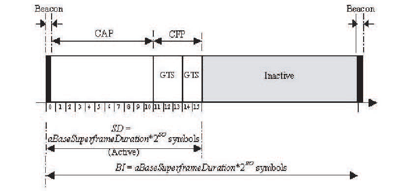
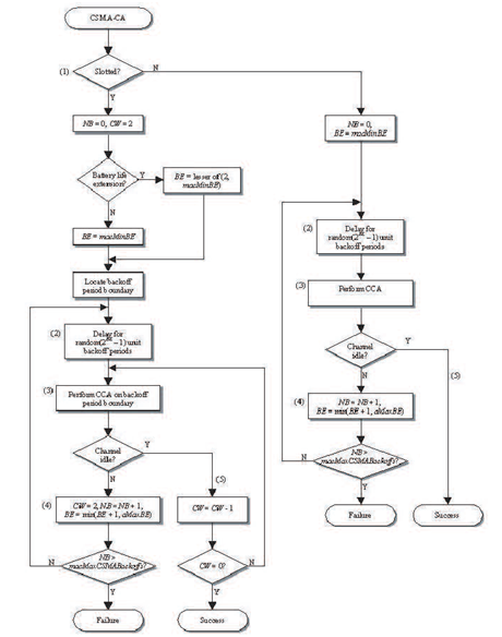
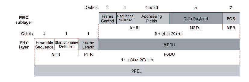
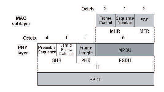
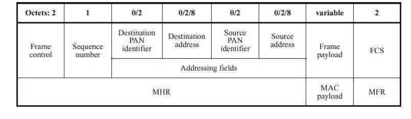
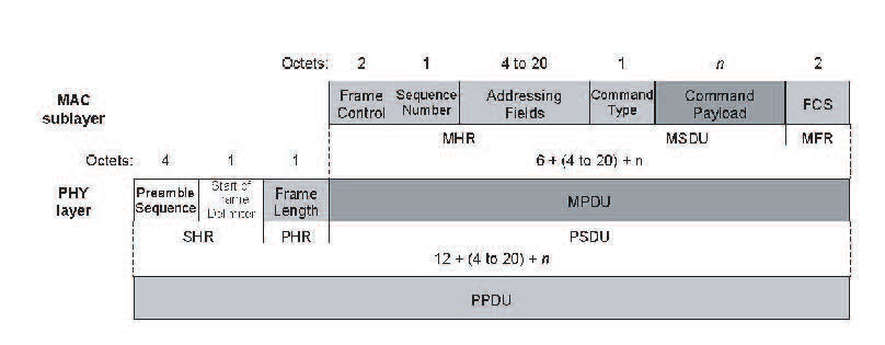
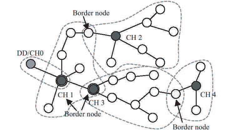
 RSS Feed

