1. IntroductionIn electric circuit star and delta circuit consist of 3 loads which in star circuit they are connected in form of a star while in delta circuit are connected in delta form as in Figure 1. 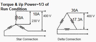
The application is usually used in (Alternate Current) AC motor where it has to start slowly. Starting the motor through a high current immediately could blow the motor as the starting current equals to the normal current multiplied by v3 (=v3 x I). It’ll be fine if the current is 5A (ampere) (I_start=v3 x 5 A=8.66 A), what happens if it’s 50A it’ll be (I_start=v3 x 50 A=86.6 A). The difference between 50A and 86.6A is quite significant. Therefore a switch to initially start a motor through star condition (low current) is needed, then after a while controlled by a time change the circuit to delta (high current). Full diagram can be seen in Figure 2. 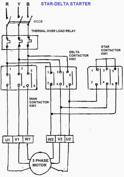
2. Simulation DesignFor the experiment here we have limited resource, we don’t have the star-delta motor which made me think whether there’s an alternative to do the star-delta motor simulation. I got an idea of using a low voltage lamp or LED as an indicator by using the brightness of the lamp. Instead I’d use 3 resistors (1 K? for this experiment) to form both star and delta circuit. We’ll see the brightness of the lamp instar and delta circuit, and for this we’ll use Direct Current (DC). Since there’s only positive (+) and negative (-) for the source we need to figure out an alternate circuit (AC have 3 sources R-S-T). For star circuit is T circuit and for delta circuit is Pi circuit in DC as shown in Figure 3 (If I have time I’ll include the calculation). Figure 3 shows that the current passed through T circuit is smaller which should be used as initial circuit, and Pi circuit passed larger current which should be switched later afterwards. 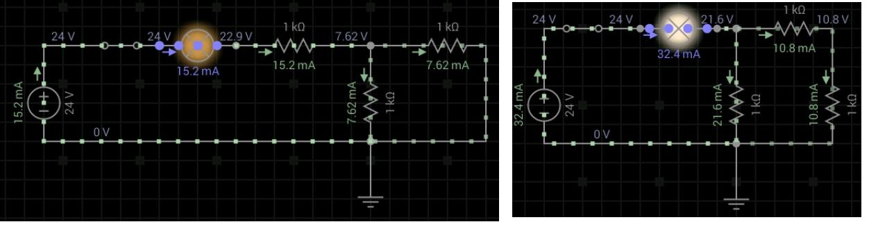
To realize this experiment we used:
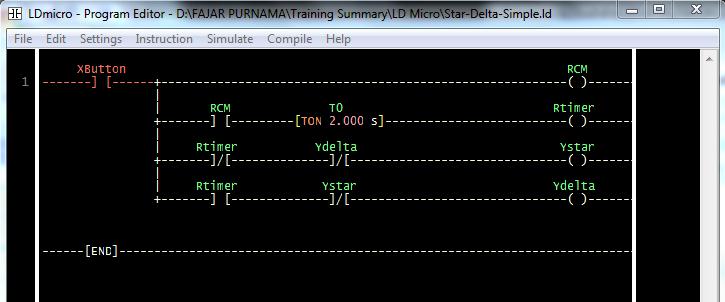
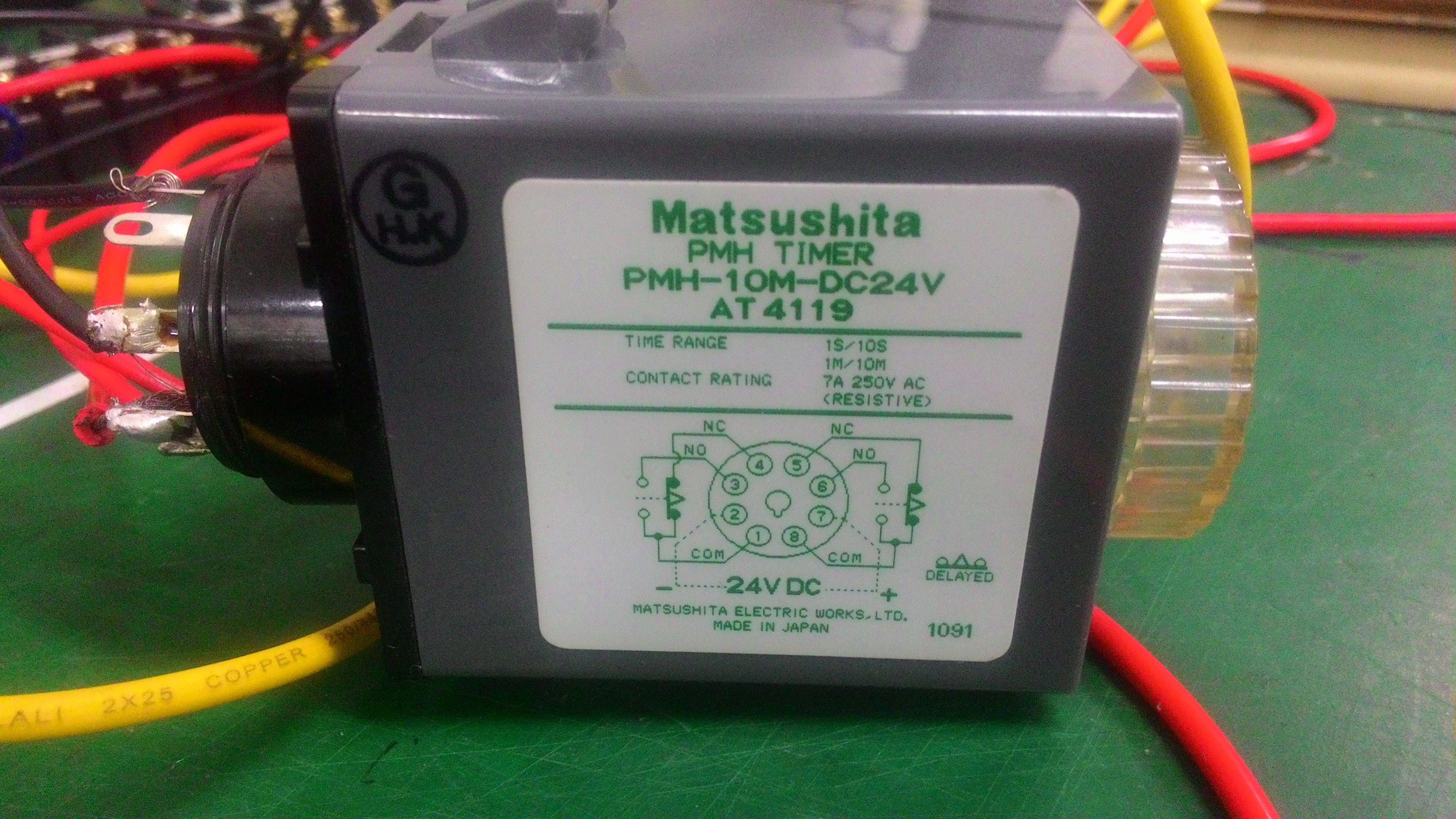
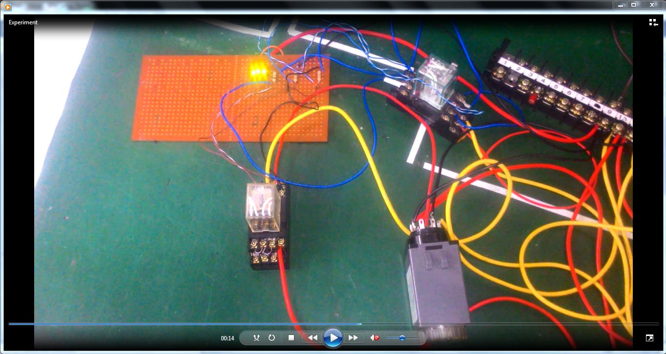
An image of a simulation can be seen on Figure 4 where 1 relay as a switch to T circuit and the other one as a switch to Pi circuit. A simulation video using android application EveryCircuit is included on this same folder as this report excluding the timer. On the real application based on the ladder diagram on Figure 5 a timer will be set where initially will start the relay of T circuit (Pi circuit disconnected). After 2 seconds (or any set time) the timer will disconnect the relay of T circuit and connecting the relay of Pi circuit. 
3. Experiment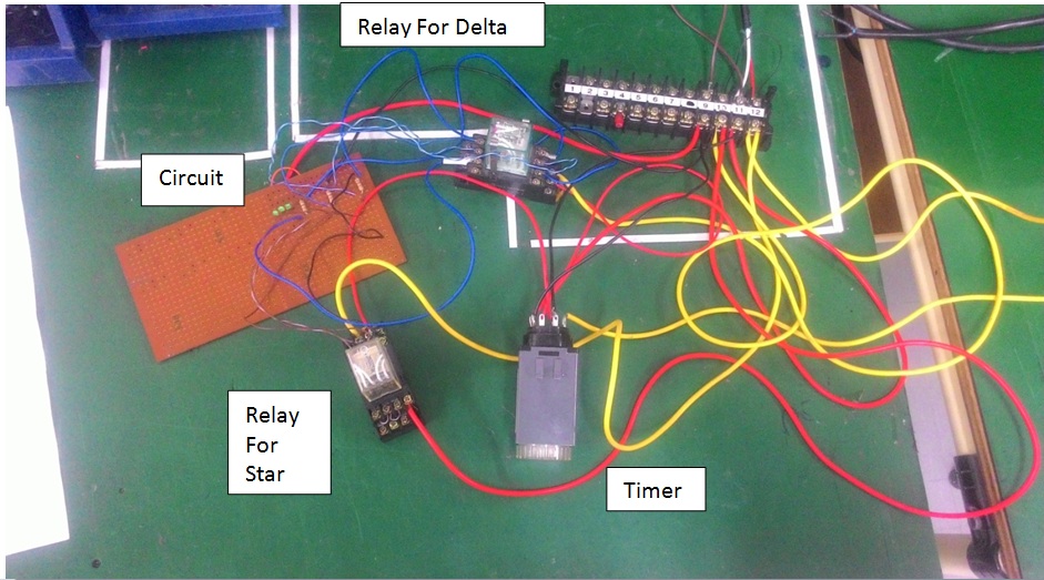
4. ConclusionThe simulation for this circuit succeeded and can be implemented to build a real star-delta motor. The motor will initially be slow, and then a few seconds the motor will be faster. This kind of design is used for devices which isn’t allowed to start at maximum power from the start (for example the motor could explode) since the initial current is v3 greater than the normal power thus a lower current is used when starting. But we want to use the device in its maximum power so a timer is needed to change the current to the maximum after passing the initial stage. Using relays and timers in terms of time we can create different conditions with just a few circuits. For example we can set the time of when we want the air conditioner to turn on or off (other machines as well).
0 Comments
Leave a Reply. |
Archives
August 2022
Categories
All
source code
old source code Get any amount of 0FP0EXP tokens to stop automatic JavaScript Mining or get 10 0FP0EXP tokens to remove this completely. get 30 0FP0EXP Token to remove this paypal donation. get 20 0FP0EXP Token to remove my personal ADS. Get 50 0FP0EXP Token to remove my NFTS advertisements! |
 RSS Feed

